
Specifications


FL-MDS-CAB.2
MOD-MDS.1 ***Confidential*** 10 of 28
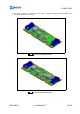
6.2 Single antenna electrical specs
1. Two identical retention connectors on the short edges of the TOP side, for CAN bus and 24 V
power supply; the connector will be JST mod. SM07B-PASS-1 (smt 7 pole side entry type header);
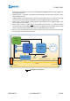
2. The CAB system allows the cascading connection of up to 32 units connected through cabling
length of maximum 6 m, providing full power supply and CAN bus connectivity;
3. The power supply to the CAB will be 24 V Dc ± 20% minus voltage drop on cabling. A switching
power unit on board is hence required;
4. The maximum estimated maximum input current is 200 mA on the 5V power rail of the CAB (137
mA for the HITAG reader plus 63 for other electronics), equivalent to 1 W. Powering each CAB
with 24 V DC – 20% (19.2 V) the maximum input power will be 60 mW per CAB. With this
consumption on 6 m / 0.14 sq. mm cabling for 32 CABs (non-distributed worst case) the voltage
drop is 3.2 V. The switching power unit must be scaled on these input characteristics.
5. The PCB has a miniaturized horizontal dip-switch with 6 lines, 5 for the CAN Id setting and 1 for
the connection of the 120 Ω termination resistor on the CAN bus. The indexes of the switches
are the bit indexes, ON switch means 1, OFF switch means 0. For example: SW1 in configuration
ON-ON-OFF-OFF-ON encodes node Id = 0b10011 = 0x0B = 11.
6. The PCB has a status green LED visible when a carrier is centered above the coil antenna. The
status of the LED is specified in the firmware section,
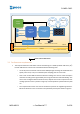
7. An electric malfunction of one CAB does not prevent the CAN communication and the power
supply to other CABs connected before and after the defective CAB. The CANopen tree master
will identify the defective CAB, the malfunctioning is managed on the CAN bus and on the power
supply bus.
8. CAB uses the MCU internal watchdog to resolve catastrophic failures.
9. The CAB has test point pads which expose the debug port of the MCU. The port is used during
firmware development and to load the factory firmware application on the MCU FLASH memory
during production.
10. The CAB PCB design documentation is completely available: circuit diagram, routing, BOM,
GERBER, in native format and PDF format.
11. Components are chosen according to Automotive Standards (10 yrs. availability min.)
12. All components except MCU and HITAG decoder are chosen to guarantee second-source supply.
6.3 Double antenna electrical specs
1. Two identical retention connectors on the short edges of the TOP side, for CAN bus and 24 V
power supply; the connector will be JST mod. SM07B-PASS-1 (smt 7 pole side entry type header);