
Specifications


FL-MDS-CAB.2
MOD-MDS.1 ***Confidential*** 4 of 28
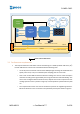
transceiver chip. The MCU is connected to an ASTMLPA-16.000MHz standard clock oscillator for
precise clock reference.
CAN transceiver – it provides the physical interface between the MCU CAN controller and the
physical CAN 2-wire bus.
HTRC110 HITAG reader chip by NXP. It drives the connected antenna to power the RFId tag,
receives the tag contents signal and sends to the CPU the digitized signal to be decoded.
Power supply – circuit subsystem which regulate and provide the correct supply voltages to the
active components of the PCB.
Antenna select circuit – present only on the double antenna version - connects the desired
antenna (A or B) to the HTRC110. It is driven by one digital line from the MCU. On the single
antenna version board the HITAG reader chip is connected directly to antenna A.
Antenna A and, on the double antenna version, Antenna B are the coil antennas which energize
the RFId tag(s) and receive data from them.
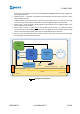
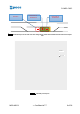
STM32
Cortex-M
MCU
HITAG RFId
reader
Antenna
A
CAN id + termination resistor
status LED
I/O connector
I/O connector
Power
supply
CAN transceiver
CAN bus
UART port
Debug port
24V DC
Figure 1. Single Antenna CAB schema