
Specifications


FL-MDS-CAB.2
MOD-MDS.1 ***Confidential*** 7 of 28
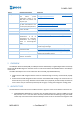
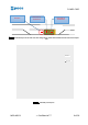
4 INTERFACES
The CAB has three hardware communication interfaces:
During normal operation the CAB communicates with other devices through the CAN port. The
default bit rate is 500 kbit/s.
The CAB MCU is programmed through the debug/programming port, which is accessed on the
PCB with test points. The port is connected to through a customized testbed of nails during
firmware development/debugging, and in production for factory programming.
The MCU has an UART port, accessible through test points, which can be connected during
firmware development for tracing and debugging purposes via the testbed of nails. The UART is
not used during normal operation.
From the system perspective the CAB is a CANopen node slave device. Therefore:
the FW application has the role of a slave CANopen node configured and queried via SDO
messages to/from its Object Dictionary.
PDO messages are used to support the normal operativity of the device itself.
A PDO message is named Received PDO (RPDO) when received by CAB.
A PDO message is named Transmitted PDO (TPDO) when transmitted by CAB.
5 RELEVANT USE CASES
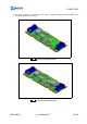
5.1 Automatic board version detection
The CAB firmware application auto detects the single/double antenna version. Therefore, if a received
command can be applied only to one of the two versions, the appropriate error or warning message will be
sent to the CANopen master.
HW version, firmware application versions and other vendor information can also be read from the CAB
CANopen Object Dictionary with SDO transactions.
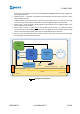
5.2 On-the-fly RFId tag reading (both versions)
During on-the-fly reading the carriers run normally on the lane. The CAB is online and one antenna is
active. The CAB sends a new carrier identified on antenna # TPDO message containing the carrier tag Id just
after the decoding. A carrier has leaved antenna # TPDO message with the same tag Id is sent just after the
RFId leaves the antenna reading range.
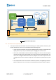
5.3 Static RFId reading of two carriers tag Ids (double antenna version)
In this use case the antennas are initially inactive (off). When the system has two carriers positioned and
centered above the two antennas the operating sequence will be:
1. activate antenna A with a RPDO1 message: the CAB will send two TPDO3s: the first one signaling
antenna A is changing state, the second one signaling antenna A activation is complete. CAB then
decodes the RFId tag and sends the carrier Id packed in a TPDO1 message;
2. deactivate antenna A with a RPDO1 message: a TPDO3 signaling antenna A deactivation is sent;
3. then CAB sends a TPDO1, signaling tag 1 Id is not read anymore.