
Specifications


FL-MDS-CAB.2
MOD-MDS.1 ***Confidential*** 8 of 28
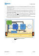
4. activate antenna B with a RPDO1 message: the CAB will send two TPDO3s: the first one signaling
antenna B is changing state, the second one signaling antenna B activation is complete. CAB then
decodes the RFId tag and sends the carrier Id packed in a TPDO2 message;
5. deactivate antenna B with a RPDO1 message: a TPDO3 signaling antenna B deactivation is sent;
6. then CAB sends a TPDO2 signaling tag 1 Id is not “read” anymore.
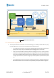
5.4 Firmware update
In this use case the CANopen master sends the new firmware package using SDO messages and reads with
SDO messages the status of the update progress. After receiving the complete package the CAB FW performs
the necessary consistency and integrity checks, then the CAB FW is ready to receive a reboot command,
which will trigger reboot and the FW update sequence on the MCU FLASH. After the reboot the CAB firmware
is ready to operate.
The FW update sequence can be repeated as needed during the normal operational life of the CAB.
5.5 HTRC110 tag reader configuration
The HTRC110 reader chip is configured each time an antenna is activated. This ensures that all the HTRC
parameters values accessible in the Object Dictionary are used as desired during tag decoding.
In simplified form a reconfiguration sequence is:
1. deactivate antennas with a RPDO1 message;
2. write the HTRC110 parameters values as desired in the relevant OD entries using SDO messages;
3. activate the desired antenna with a TPDOn message.
6 DESIGN SPECIFICATIONS REFERENCE – MECHANICAL AND ELECTRICAL
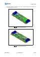
6.1 CAB mechanical specification
The following mechanical specifications are mandatory requirements for both versions:
1. CAB can be mounted inside the track profile of Inpeco automation systems.
2. CABs single and double antenna version are produced using the same PCB populated differently
3. The dimensions must be as small as possible, with the following limits:
4. Maximum width 20 mm;
5. Maximum length 80 mm;
6. PCB thickness 1 mm (39-40 mil)
7. Top components maximum height 8 mm
8. Bottom components maximum height 4 mm
9. The PCB is designed to have the double antenna with antennas axes at a distance of 40 mm
(carrier step).
10. The PCB has asymmetric mounting buttonholes to ensure correct mounting direction during FW
programming and field encasing in the plastic support
11. the PCB has an etched arrow to show belt direction
Double antenna version requirements follow:
12. N double antenna CABs can be physically and electrically connected to form a linear array of
antennas separated by 40-mm gaps, creating 2*N contiguous sampling points