ISP4520 Smart LoRa and Bluetooth Low Energy Module with MCU and Antennas This highly miniaturized LGA module, 9.8 x 17.2 x 1.7 mm, is based on the new SX126x LoRa transceiver series and nRF52832 BLE chip. Using a simple user interface via the SPI connection and integrating a Cortex™ M4 CPU, flash and RAM memory combined with single optimized antenna for both LoRa and BLE standards, ISP4520 offers the perfect stand-alone module solution for large spectrum of application in IoT domains.
LoRa / BLE MODULE ISP4520 Revision History Revision Date Ref Change Description R0 25/01/2018 hc pg Preliminary release R1 17/05/2018 hc pg Engineering sample release R2 05/07/2018 hc pg Schematic & IO changes R3 21/02/2019 hc pg RF performance update R4 16/10/2019 jf pg RF specification update, addition of §5 and §6 R5 13/02/2020 nw pg JP variant extended to Asia Pacific zone, called AS R6 06/04/2020 ys pg EU Variant Engineering E US and AS Variant Engineering B Electrical s
LoRa / BLE MODULE ISP4520 Contents 1. Block Diagram ............................................................................................................................................................... 4 2. 2.1. 2.2. 2.3. 2.4. 2.5. 2.6. 2.7. 2.8. 2.9. 2.10. Specifications ................................................................................................................................................................ 4 Important Notice .............................................
LoRa / BLE MODULE ISP4520 1. Block Diagram This module is based on the Semtech SX126x single-chip LoRa transceiver series and the nRF52832 Nordic Semiconductor 2.4GHz wireless System on Chip (SoC). It integrates a 32-bit ARM Cortex™ M4F CPU, flash memory as well as analog and digital peripherals. ISP4520 can support LoRa connectivity compliant to LoRa Alliance standards.
LoRa / BLE MODULE ISP4520 2.1. Important Notice The electrical specifications of the module are directly related to the Semtech SX126x series transceiver and the Nordic Semiconductor nRF52832 specifications for chipsets. The information below is only a summary of the main parameters. For more detailed information, please refer to the up-to-date specification of chipsets available on Semtech and Nordic Semi website. The LoRa part of the modules is designed to work according to the LoRaWan specifications.
LoRa / BLE MODULE ISP4520 2.4. Current Consumption Parameter Min Typ Max Unit LoRa current, Receiver active (1) 4.6 mA LoRa current, Transmitter active, EU and AS variant (2) 25.5 mA LoRa current, Transmitter active, US variant (3) 118 mA LoRa standby mode, no oscillator active 0.6 mA LoRa sleep mode, with warm start 600 nA LoRa off mode 160 nA BLE Peak current, Receiver active (4) 6.1 mA BLE Peak current, Transmitter active +4 dBm Output Power (5) 7.
LoRa / BLE MODULE ISP4520 It can be used in European Union countries, India, Russia and most of the Middle East and Africa. Parameter - EU variant Min LoRa Frequency Band (EU) 863 LoRa Rx sensitivity Level for BER <1% (3) -137 LoRa Output Power at transceiver output LoRa Antenna Gain in band Max Unit 870 MHz dBm +14 (1) (5) LoRa Load impedance LoRa Range Open field @ 1 m height Typ (1) (3) (5) LoRa Range Open field @ 1 m height (2) (3) dBm -2.
LoRa / BLE MODULE ISP4520 Parameter Min BLE Frequency Range 2402 BLE Channel 0 to 39 Spacing Typ Max Unit 2480 MHz 2 BLE Output Power Channels 0 to 39 -20 BLE Rx sensitivity Level for BER <0,1% ideal Tx -96 BLE Antenna Gain MHz +4 dBm -3.6 BLE EIRP -23.6 BLE Range Open field @1m height (1) dBm dBi 0.4 70 dBm m (1) Data Rate 1000 / 2000 Kbps 2.8.
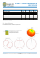
LoRa / BLE MODULE ISP4520 LoRa Radiation Pattern – Module in top center edge Module positioned on the center of the top edge of the application PCB (top view) Keep out zone of 50 mm length Ground plane of 70 x 50 mm Ground Plane Effect Simulation Top left position Ground plane 70 x 50 mm Top left position Ground plane 50 x 40 mm Top center position Ground plane 70 x 50 mm Top right position Ground plane 70 x 50 mm Top left position Ground plane 40 x 70 mm January 13, 2021 Document Ref: isp_lora_DS45
LoRa / BLE MODULE ISP4520 January 13, 2021 Document Ref: isp_lora_DS4520_R7 Page 10/31 Insight SiP – Green Side – 400 avenue Roumanille – BP 309 – 06906 Sophia-Antipolis Cedex – France – www.insightsip.
LoRa / BLE MODULE ISP4520 2.9. Electrical Schematic Details of Semtech LoRa transceiver connections - Note that EU and AS variants are based on SX1261, L9 inductance is mounted but R3 resistor is not. - US variant is based on SX1262, R3 resistor is mounted but L9 inductance is not. January 13, 2021 Document Ref: isp_lora_DS4520_R7 Page 11/31 Insight SiP – Green Side – 400 avenue Roumanille – BP 309 – 06906 Sophia-Antipolis Cedex – France – www.insightsip.
LoRa / BLE MODULE ISP4520 Details of nRF52832 connections, based on nRF52832 January 13, 2021 Document Ref: isp_lora_DS4520_R7 Page 12/31 Insight SiP – Green Side – 400 avenue Roumanille – BP 309 – 06906 Sophia-Antipolis Cedex – France – www.insightsip.
LoRa / BLE MODULE ISP4520 2.10. Internal Module Connections The following nRF52 pins are used to communicate with the SX126x and therefore must not be configured to do anything else. nRF Pin name SX126x Pin name Description P0.11 P0.19 P0.23 P0.24 P0.25 P0.26 P0.
LoRa / BLE MODULE ISP4520 3. Pin Description The module uses an LGA format. The pad layout follows the QFN Jedec standard for LGA parts. The NC pads are to be connected to isolated metal pads on the application PCB for mechanical stability and reliability (drop test).
LoRa / BLE MODULE ISP4520 Pin Name Pin function Description 31 32 33 34 GND GND GND BLE_ANT Ground Ground Ground RF I/O 35 BLE_TR RF I/O Power Ground – Must be connected to ground on application PCB Power Ground – Must be connected to ground on application PCB Power Ground – Must be connected to ground on application PCB Internal BLE antenna RF I/O pin Should be connected to Pin 35 for normal operation BLE RF I/O pin of the module Should be connected to Pin 34 for normal operation Power Ground –
LoRa / BLE MODULE ISP4520 4. Mechanical Outlines 4.1. Mechanical Dimensions Dimensional drawing for 9.8 x 17.2 x 1.7 mm, 74-Pad LGA Package January 13, 2021 Document Ref: isp_lora_DS4520_R7 Page 16/31 Insight SiP – Green Side – 400 avenue Roumanille – BP 309 – 06906 Sophia-Antipolis Cedex – France – www.insightsip.
LoRa / BLE MODULE ISP4520 Detail of LGA package pad positioning and size January 13, 2021 Document Ref: isp_lora_DS4520_R7 Page 17/31 Insight SiP – Green Side – 400 avenue Roumanille – BP 309 – 06906 Sophia-Antipolis Cedex – France – www.insightsip.
LoRa / BLE MODULE ISP4520 4.2. SMT Assembly Guidelines For PCB Land Patterns and Solder Mask layout, Insight SiP recommends the use of the same dimensions as the module pads, i.e. 0.65 x 0.30 mm for standard pads, 0.70 x 0.70 mm for corner pads, 2.75 x 2.15 mm for mechanical pads. Please contact Insight SiP for more detailed information. 4.3.
LoRa / BLE MODULE ISP4520 5. Product Development Tools 5.1. Hardware In order to assist clients in developing their solutions based on the ISP4520, Insight SIP offers an Evaluation Board containing: One Interface Board with J-Link Seeger integrated SWD/JTAG interface One Test Board One Rx Gateway Board Cables Using this evaluation board, product developers can use a working solution as starting point to develop their own products. Time to market is saved by avoiding starting from a blank sheet of paper.
LoRa / BLE MODULE ISP4520 5.3. Development Tools The following development tools and software are recommended for using and testing the ISP4520 module: Nordic Semiconductor nRFgo Studio or nRF Connect for Desktop: Downloadable after registering at www.nordicsemi.com. Debugging and IDE: SEGGER Embedded Studio (SES): Downloadable from https://www.segger.com/products/development-tools/embedded-studio/ Keil MDK-ARM Lite (limited to 32 KB code) Downloadable from https://www.keil.com/demo/eval/arm.htm.
LoRa / BLE MODULE ISP4520 6. Reference Design 6.1. Sensor Board Design The ISP4580 is an autonomous low-power device for wireless acceleration, temperature, light and barometer detection. The complete device makes use of Insight SiP ISP4520 module together with low power Accelerometer/Magneto, Humidity/Temperature and Barometer sensors connected to a primary button cell battery CR2032.
LoRa / BLE MODULE ISP4520 USB Connections January 13, 2021 Document Ref: isp_lora_DS4520_R7 Page 22/31 Insight SiP – Green Side – 400 avenue Roumanille – BP 309 – 06906 Sophia-Antipolis Cedex – France – www.insightsip.
LoRa / BLE MODULE ISP4520 Power Supply January 13, 2021 Document Ref: isp_lora_DS4520_R7 Page 23/31 Insight SiP – Green Side – 400 avenue Roumanille – BP 309 – 06906 Sophia-Antipolis Cedex – France – www.insightsip.
LoRa / BLE MODULE ISP4520 7. Packaging & Ordering information 7.1. Marking ISP4520EU M /N : I S P 4 5 2 0 T T Y Y W W R M/N: ISP4520 EU YYWWE ISP4520US M/N: ISP4520 US YYWWB IC: 11306A-ISP4520US FCC ID: 2AAQS-ISP4520US ISP4520AS M/N: ISP4520 AS YYWWB R 018-200315 ISP4520 YY Part Number 2 letters Module Type (see section 7.5) 2 digits year number WW 2 digits week number R 1 letter Hardware revision TT 7.2.
LoRa / BLE MODULE ISP4520 7.3. Jedec Trays For higher quantities and volume production, ISP4520 are available in Jedec trays. They are delivered in sealed pack with desiccant pack and humidity sensors. These Jedec trays are also suitable for further baking. Please see section 8.2 for more information on moisture sensitivity. Jedec trays are proposed in standard quantities of 100 units, 200 units and multiples of 200 units only.
LoRa / BLE MODULE ISP4520 7.4. Tape and Reel ISP4520 are also available in Tape & Reel. They are delivered in sealed pack with desiccant pack and humidity sensors. Reels are proposed in standard quantities of 500 units (180mm / 7” reel) or 2000 units (330mm / 13” reel) only. Please order with “RS” code packaging suffix for 500-unit reels and “R2” for 2000-unit reels. Complete information is available on request. 7.5.
LoRa / BLE MODULE ISP4520 8. Storage & Soldering information 8.1. Storage and Handling Keep this product away from other high frequency devices which may interfere with operation such as other transmitters and devices generating high frequencies.
LoRa / BLE MODULE ISP4520 8.3. Soldering information Recommendation for RoHS reflow process is according to Jedec J–STD-020 and 033 standard profiles.
LoRa / BLE MODULE ISP4520 9. Quality & User information 9.1. Pending Certifications FCC Identifier 2AAQS-ISP4520US IC Identifier 11306A-ISP4520US CE: Complies with 1999/5/EC, EN300328 V1.9.1 – EC DoC N° tbd Bluetooth SIG certified N° tbd RoHS compliant 9.2. USA – User information This intends to inform how to specify the FCC ID of our module “ISP4520” on the product. Based on the Public Notice from FCC, the host device should have a label which indicates that it contains our module.
LoRa / BLE MODULE ISP4520 The label of the host device should also include the below IC Statement. When it is not possible, this information should be included in the User Manual of the host device: “This device complies with Industry Canada licence-exempt RSS standard(s). Operation is subject to the following two conditions: (1) this device may not cause interference, and (2) this device must accept any interference, including interference that may cause undesired operation of the device.
LoRa / BLE MODULE ISP4520 9.7. Disclaimer Insight SiP’s products are designed and manufactured for general consumer applications, so testing and use of the product shall be conducted at customer’s own risk and responsibility. Please conduct validation and verification and sufficient reliability evaluation of the products in actual condition of mounting and operating environment before commercial shipment of the equipment.