
Installation Guide

7
PROPERTY DAMAGE
These plumbing instructions were written for an
experienced competent installer. If the installer
is not experienced in plumbing installation,
InSinkErator recommends that competent
professional assistance is sought. Damage to
the disposer or accessories as a result of
improper installation is not covered under
warranty. All installations must comply with local
plumbing codes.
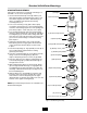
Plumbing Connections
DRAIN LINE CONNECTIONS
To allow easy access to overload reset button, the
disposer plumbing should be connected with the
electrical control box facing the operator.
When connecting the drain line, place the "P-trap" as
close to the disposer outlet flange as possible. Do not
connect the drain line to a grease trap, interceptor, or
drum trap.
All horizontal runs should be as short as possible, with a
minimum fall of 1/4 inch per foot.
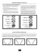
WATER SUPPLY CONNECTIONS
When connecting the disposer to the incoming water
supply, use as few elbows and tees as possible.
Connect to the cold water line only. All water line
fittings are 1/2" NPT except the sink bowl nozzles
(1/2" compression).
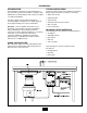
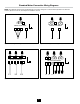
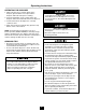
Install the flow control valve, water solenoid valve, and
the syphon breaker according to the direction of the
flow arrows marked on each valve body (see Figure 9).
NOTE: A syphon breaker must be installed above the
sink flood plane per local plumbing codes.
ROUTING WATER FLOW
• In a trough system, route all water flow to the end of
the trough to flush food waste.
• In a sink bowl system route all water through the
sink bowl.
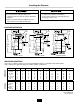
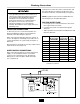
• Table 2 provides Recommended Cold Water Flow and
Drain Line Diameter.
Disposer Standard
Flow Control
GPM (LPM)
Optional
Flow Control
GPM (LPM)
Drain
Line
Diameter
SS-50 3 (11) NA 1-1/2"
SS-75 3 (11) NA 1-1/2"
SS-100 5 (19) 3 (11) 1-1/2"
SS-125 5 (19) 3 (11) 2" NPT
SS-150 7 (26) 5 (19) 2" NPT
SS-200 7 (26) 5 (19) 2" NPT
SS-300 8 (30) 7 (26) 3" NPT
SS-500 8 (30) 7 (26) 3" NPT
SS-750 10 (38) NA 3" NPT
SS-1000 10 (38) NA 3" NPT
Table 2. Recommended Cold Water Flow
and Drain Line Diameter
Figure 9. Installation Diagram