
Installation Guide

8
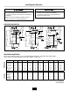
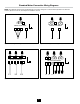
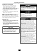
Standard Motor Connection Wiring Diagrams
NOTE: The diagrams below show standard motor connection wiring for a manual switch operation. For alternate
controls, please refer to the control panel installation manual.
4 5 6
MOTOR LEAD WIRE#
L2
2
L1
7
31
L1
L2 L3
1
4 10 5 6 12
MOTOR LEAD WIRE#
11
7 2 8 3 9
2 3 4
MOTOR LEAD WIRE#
L1
7
L2
1
5 6
1
4 7 5 6 9
MOTOR LEAD WIRE#
L1 L2 L3
8
2 3 10 11 12
Figure 12. Incoming 208-230V Three Phase Line Power
Figure 10. Incoming 115V Single Phase Line Power Figure 11. Incoming 208-230V Single Phase Line Power
Figure 13. Incoming 460V Three Phase Line Power