
Installation Sheet

c
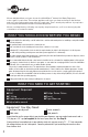
Property Damage: Do not extend the lines farther
than the 16” provided. Ensure tube(s) and “Y”
connector are securely fit.
Personal Injury: Do not locate filter above an outlet or other
electrical device. Install head and bracket so that connections
require no stretching, kinking or pinching of tubing.
It is normal for approximately 2 oz. of water to
discharge when filter is removed.
Property Damage: Tube runs need to form to the cabinet’s
contours to allow storage space with no sharp bends. Tubes
need clean, perpendicular, burr-free cuts to ensure a true fit.
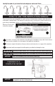
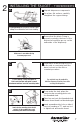
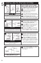
a
Determine length of tubing required,
then cut to length making sure the cut
is perpendicular and burr-free.
Insert a white 1/4" tube into inlet side
of filter head until it stops. Press in
again to ensure a secure fit.
Insert the other white 1/4" tube into
outlet side of filter head until it stops.
Press in again to ensure a secure fit.
Separate cartridge from filter head.
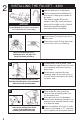
Mark hole locations for filter head
and bracket in a spot that allows
for filter replacement.
Drill 1/8" starter holes and attach bracket
to wall with wood screws, turning until snug.
Insert cartridge into filter head. Top
surface of cartridge will become flush with
bottom of filter head when fully engaged.
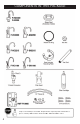
Connect remaining white 1/4" tube to
incoming water supply line.
(See Step 6.)
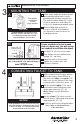
Insert the copper tubes(s) from the
dispenser into “Y” quick-connector
using the plug for hot-only models.
Connect the white 1/4" tube from
the right outlet on the filter head into
the quick-connect fitting until it stops.
Press in again to ensure a secure fit.
To remove tube(s) or plug from quick-connector,
depress the release ring and gently pull away.
d
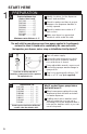
5
INSTALLING FILTRATION SYSTEM
Screws provided are for use in wood
studs or cabinets only. Use wall anchors
(not supplied) for installation into drywall.
b
10
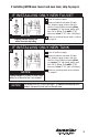
HC1100, HC2200,
HC2215
GN1100, GN2200, GN2215,
HC3300, H3300
NOTICE
NOTICE