
Installation Guide

INSTALOCK
Congratulations on purchasing the Instalock remote control unit for your existing thumb-turn deadbolt lock.
The Instalock unit works on existing deadbolts by transforming your existing lock into a remote-controlled door lock. Installation is
simple with NO TOOLS REQUIRED.
BOTH YOUR DOOR KEY AND YOUR THUMB-TURN WILL OPERATE YOUR DOOR LOCK MANUALLY. WE RECOMMEND THAT YOU
ALWAYS CARRY YOUR KEY WITH YOU WHEN LEAVING YOUR HOME. ALWAYS MAKE SURE TO CHECK YOUR DOOR IS LOCKED
WHEN USING YOUR INSTALOCK REMOTE CONTROL UNIT TO LOCK YOUR DOOR.
THE INSTALOCK UNIT WILL NOT FUNCTION CORRECTLY IF YOU HAVE TO PUSH OR PULL YOUR DOOR WHEN USING YOUR KEY
TO OPEN OR LOCK YOUR DOOR. WE RECOMMEND CONSULTING A PROFESSIONAL TO ADJUST YOUR EXISTING LOCK MECHA-
NISM SO THAT YOUR EXISTING DOOR LOCK OPERATES SMOOTHLY.
FOR VIDEO INSTRUCTIONS ON HOW TO ADJUST YOUR EXISTING DOOR LOCK YOURSELF, AND FOR VIDEO INSTALLATION
INSTRUCTIONS, PLEASE VISIT WWW.INSTALOCK.COM
CONTENTS:
1 Instalock unit 1 Metal Plate with adhesive strips (attached to unit) 1 Remote control
4 AA Batteries 4 Adhesive Strips 2 Sticky tabs
Preparing Your Doors Surface
Clean the area around your thumb turn door lock with rubbing alcohol prior to installing the Instalock unit.
Your Instalock unit is paired and ready for use with the enclosed remote control. Remove the battery tab from the battery compart-
ment to activate the batteries. Your Instalock is now ready for use. To pair additional remote control units please follow the steps
provided under “Remote Pairing”.
METAL DOOR SURFACES
To determine if you have a metal door, hold the Instalock unit against the doors surface. If you feel a magnetic pull towards the door,
then you may proceed to install the Instalock unit as follows:
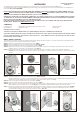
STEP 1.
Remove the metal plate from the back of the unit. (FIG.1)
STEP 2. Turn the thumb-turn to its most horizontal position (FIG.2a. FIG.2b)
STEP 3. Align the thumb-turn with the corresponding C channel (FIG.3)
STEP 4. Attach the unit over your existing dead bolt thumb turn. Adjust the unit so that it aligns squarely with your doors surface,
making sure the C channel fits over the thumb- turn.(FIG. 4)
STEP 5. Remove the Instalock unit from the metal door by turning the unit at an angle to release the magnetic attachment.
DO NOT pull the unit directly from the door. Slide the unit clockwise, or counter clockwise to release it easily from the doors
surface.
NON-METAL DOOR SURFACES
STEP 1. Turn the thumb-turn to its most horizontal position. (FIG.2a. FIG.2b)
Practice aligning the C channel over the thumb-turn prior to removing the adhesive strips. It is important to make sure the C
channel fits over the thumb turn and is horizontal to your doors surface prior to installing.
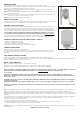
STEP 2. Remove the adhesive backing from the metal plate. (FIG.5)
STEP 3. Align the thumb-turn with the corresponding C channel. (FIG.6)
STEP 4. Make sure the C channel is aligned over the thumb- turn and the unit is aligned squarely to your doors surface. Press the unit
firmly against the door surface for 10 seconds. (Fig.7) The metal plate should now be secured to your doors surface.
Step 5. Remove the Instalock unit from the metal plate by turning the unit at an angle to release the magnetic attachment. DO NOT
pull the unit directly from the door. Slide the unit clockwise, or counterclockwise to release it easily from the doors surface.
The metal plate should now be secured to your doors surface. (FIG. 10)
FIG.10
FIG.9
REMOTE PAIRING
Your Instalock unit is paired and ready for use with the enclosed remote control.
Your Instalock can pair with up to a maximum of eight remotes. In order to pair additional remote
controls to your unit please follow the instructions below:
STEP 1. Make sure the battery tab located on the battery compartment has been removed to
activate the batteries.
STEP 2. Press and hold the program button for two seconds (Fig8). The red light on the front of
the unit will turn red.
STEP 3. Press any key on the remote control, the LED light will flash 12 times. Once the LED light
turns off, the remote is now paired to your unit.
STEP 4. Reattach the unit to your doors surface.
REMOTE UNPAIRING
Press the pairing button, the red light will turn on. After pressing the pairing button for 10 seconds
the red light will turn off. Your Instalock is now unpaired from the remote control.
POLARITY SWITCH SETTING
Home doors are both left-handed and right-handed. You may need to change the direction of
the Instalock unit's function to accommodate your door lock opening in the correct direction.
If you have purchased a proximity remote control separately, or an Instalock 4 digit keypad to
open your door, you may need to change the polarity switch to attain the correct opening signal.
YOUR INSTALOCK UNIT COMES WITH A PRESS BUTTON REMOTE CONTROL. IF YOU WISH
TO PURCHASE A PROXIMITY REMOTE, OR 4 DIGIT KEYPAD PLEASE VISIT INSTALOCK.COM
If you wish to use the round button on your remote control to open your door, you may need to
change the polarity switch depending on whether you door is a left-hand or right hand-door.
CHANGING THE DIRECTION OF THE POLARITY SWITCH
1. Remove one battery from the unit.
2. Change the polarity switch (FIG.8)
3. Wait 10 seconds before replacing the battery.
4. The Instalock unit will now turn in the opposite direction.
CHANGING BATTERIES
The Instalock unit comes with 4 AA batteries.
You may change the batteries (Which are located in the battery compartment at the back of
the unit) when the unit requires more than two presses of the remote control button to unlock
your door.
UNIT MOVES WHEN ACTIVATED
If your unit should move slightly during operation, apply the enclosed sticky pads as follows:
Apply a sticky pad to the two upper magnets of the Instalock unit. Once you have applied the sticky pad to each magnet remove the
top liner. Reattach the unit to your doors surface.
METAL PLATE REMOVAL
Place one hand on the metal plate to secure while removing.
Pull down on the exposed adhesive tabs at a 45 degree angle, making sure the surface of
the adhesive strip remains flush against the door surface as you pull downwards. (Fig.9)
DO NOT ATTEMPT TO REMOVE THE METAL PLATE WITHOUT FOLLOWING THE INSTRUCTIONS. YOU MAY DAMAGE YOUR DOORS
SURFACE WITHOUT FOLLOWING THE INSTRUCTIONS. GO TO INSTALOCK.COM FOR VIDEO INSTRUCTION.
100% SECURE
THE INSTALOCK REMOTE CONTROL UNIT USES THE SAME TECHNOLOGY AS YOUR AUTOMOBILE REMOTE CONTROL. THE
INSTALOCK IS EQUIPPED WITH ROLLING CODE TECHNOLOGY. EACH TIME YOUR UNIT IS ACTIVATED THE CODE CHANGES TO A
NEW ACCESS CODE.
WARNING: THE INSTALOCK UNIT CONTAINS STRONG MAGNETS. KEEP AWAY FROM CHILDREN UNTIL THE UNIT IS ATTACHED TO
YOUR DOORS SURFACE.
WARNING: WHEN USING YOUR INSTALOCK REMOTE TO LOCK YOUR DOOR, ALWAYS CONFIRM THAT YOUR DOOR IS LOCKED.
Caution: Any changes or modifications to this device not explicitly approved by manufacturer could void your authority to operate
this equipment.
Note: This equipment has been tested and found to comply with the limits for a Class B digital device, pursuant to part 15 of the FCC
Rules. These limits are designed to provide reasonable protection against harmful interference in a residential installation. This
equipment generates, uses and can radiate radio frequency energy and, if not installed and used in accordance with the instructions,
may cause harmful interference to radio communications. However, there is no guarantee that interference will not occur in a particular
installation.
If this equipment does cause harmful interference to radio or television reception, which can be determined by turning the equipment
off and on, the user is encouraged to try to correct the interference by one or more of the following measures:
• Reorient or relocate the receiving antenna.
• Increase the separation between the equipment and receiver.
• Connect the equipment into an outlet on a circuit different from that to which the receiver is connected.
• Consult the dealer or an experienced radio/TV technician for help.
Caution: Any changes or modifications to this device not explicitly approved by manufacturer could void your authority to operate
this equipment.
PATENT NO. 10087656 / 10273718