Micro Dimmer Owner’s Manual 2442-222 (US) 2442-422 (EU) 2442-522 (AUS/NZ) North America EU/AUS/NZ Page 1 of 24 2442-222/2442-422/2442-522 - Rev: 1/21/2014 8:00 AM
About Micro Dimmer ................................................................................................................................... 4 Features and Benefits ............................................................................................................................... 4 Before Installation .......................................................................................................................................
Limited Warranty ..................................................................................................................................... 23 Limitations................................................................................................................................................
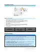
About Micro Dimmer LED Sense #1 (yellow) Sense #2 (purple) Antenna (secured for shipping purposes) Features and Benefits - Integrated dimmer featuring 32 dim levels and 32 ramp rates Wires in behind existing wall switch or in fixture box (requires neutral wire) Compatible with latching, single momentary and dual momentary switches Sense wires allow local control from any standard wall switch Can contain up to 400 controller/responder links X10 compatible All settings preserved in non-volatile memory, ev
specifications. If this device supports dimming, please note that dimming an inductive load, such as a fan or transformer, could cause damage to the dimmer, the load bearing device, or both. If the manufacturer of the load device does not recommend dimming, use a non-dimming INSTEON on/off switch. USER ASSUMES ALL RISKS ASSOCIATED WITH DIMMING AN INDUCTIVE LOAD.
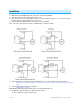
Installation Write down the INSTEON ID found on the back of the unit (XX.XX.XX) Turn off breaker/fuse and verify that the power is off Disconnect wires from existing switch, fixture or outlet and prep all wires to be connected to Micro module, with 3/16” (5mm) of bare wire on the ends 4) Connect wires per diagram which corresponds to your installation Note: sense lines carry very low current (~0.35mA 240V, ~0.
LED will start blinking green Press and hold set button until it beeps a second time LED will start blinking red c) Press and hold set button until it beeps a third time LED will start blinking green d) Perform the step that applies • For single momentary: slowly tap set button four times LED will continue blinking green • For dual momentary: slowly tap set button five times LED will start double-blinking green • To switch back to latching: slowly tap set button six times LED will start blinking green e) On
Change to Latching Mode (default) 1) Press and hold set button until it beeps LED will start blinking green 2) Press and hold set button until it beeps a second time LED will start blinking red 3) Press and hold set button until it beeps a third time LED will start blinking green 4) Slowly tap set button six times LED will continue blinking green 5) Press and hold set button until it double-beeps LED will stop blinking 6) Test mode change by tapping switch on and off Load will respond appropriately 3-Way T
Local Control Operation Micro module’s switch operation mode affects how it responds to commands from the switch. This is why it’s important to program Micro module for the specific type of switch you are using. Micro module’s on/off buttons function exactly like the top and bottom of your wall switch. Latching Switch (Default) Note that this table refers to the latching switch operation if 3-way toggle mode is disabled (it is enabled by default).
Adjust Local Settings Local On-Level The local on-level is the brightness at which the connected load will come on when turned on at the switch wired into Micro module. The default on-level is 100% brightness, but it can be set to any one of 32 fixed brightness levels (3% to 100%) or “resume dim” (brightness prior to last being turned off).
Ramp Rate Presets “Instant” 0.5 seconds (factory default) 2 seconds 5 seconds 9) Test by turning off and then back on via the local switch Light will ramp off and back on at the new local ramp rate Resume Dim When resume dim is enabled, each time you turn on Micro module it will go to the previously used dim level. By default, Micro module will come on at 100% brightness, but to change the desired level, simply follow the instructions below.
Error Blink Default = enabled This setting is only adjustable via software or a central controller. Micro module LED will blink red once for a few seconds if one or more responders do not acknowledge a message and will blink green once if all responders are successful. Blink on Traffic Default = disabled This setting is only adjustable via software or a central controller. Micro module LED will blink red if it detects noise that could disrupt communication.
Configure INSTEON Settings Most Micro module links and settings can be configured locally—during installation with the module’s set button or after installation using the switch connected to the module. All Micro module settings can be managed remotely via software (sold separately). Make Micro Module a Responder (Set button) Note: you must perform these steps before reinstalling the wall switch or fixture.
Make Micro Module a Controller (Switch) 1) Quickly tap switch connected to Micro module exactly five times in less than four seconds. (If using a latching or dual momentary switch, alternate switch directions: up-down-up-down-up or down-updown-up-down.) After tapping switch, wait two seconds.
Make Micro Module a Controller of Multiple Responders 1) Press and hold Micro module set button until it beeps LED will start blinking green 2) Tap Micro module set button LED will start double-blinking green 3) For each responder you are adding: a. Adjust responder to desired scene brightness/state b.
Micro module will beep and LED will stop blinking 6) Test by tapping the switch wired into Micro module on and off None of the former responders will respond Factory Reset All settings and scenes will be erased and return to factory default settings.
Specifications General Product name Micro Dimmer Brand/manufacturer INSTEON Manufacturer product number US 2442-222 EU 2442-422 AUS/NZ 2442-522 US 813922012705 UPC EU 813922012712 813922012729 Warranty AUS/NZ 2 years, limited INSTEON INSTEON Controller and responder Maximum links/scenes 400 Load brightness levels 32 locally (256 with software) Green when load is on, red when load is off Status LED Blinks red once when responder does not acknowledge/blinks green once if all responder
RF Range Up to 50 meters (150 feet) open air* *Range may vary due to local interference/building construction Phase detect beacon Yes INSTEON Device Category 0x01 Dimmable Lighting Control (All Frequencies) INSTEON Device Subcategory 2442-222 (915 MHz) 0x35 2442-422 (869 MHz) 0x38 2442-522 (921 MHz) 0x39 X10 X10 address 1 optional (comes unassigned) X10 transmitter Yes X10 receiver Yes X10 status response Supported X10 resume dim Supported (by setting local on-level to zero) X10 minim
Storage temperature range o o o o -4 to 158 F (-20 to 70 C) Electrical Voltage 100VAC to 240VAC Frequency 50/60Hz auto-detected at power-up Maximum load 200 Watts (@ 240VAC) 200 Watts (@ 120VAC) Minimum load 5 Watts Load type(s) Incandescent Hardwired remote control Yes, either latching or momentary switches supported Retains all settings without power Yes, saved in non-volatile EEPROM Standby power consumption < 1 watt Safety approved ETL, CE, C-Tick FCC 15.107, 15.109, 15.
Troubleshooting Problem Possible Cause Solution Make sure the circuit breaker is turned on The LEDs on Micro Micro module is not getting module are not turning on power at all The switch I’m replacing only has two wires Check junction box wires to ensure all connections are tight and no bare wires are exposed Check the light fixture to ensure all connections are tight and no bare wires are exposed Look in the rear of the junction box for a group of wires tied together with a wire nut.
light with another controller, the light will turn on, then back off with an INSTEON on-level at a high brightness and an X10 Remove the X10 address from INSTEON address on-level at a low controller brightness When I press a button on Micro module, it takes a long time for other INSTEON devices it is controlling to respond Connect power to the responder Micro module is trying to control a responder that is not If the INSTEON device is still available, remove it from Micro module and then re-add it respon
Stuck/Disabled Buttons If Micro module’s buttons are not responding, they may have been disabled due to a stuck button. If any button is pressed during power-up, or after power-up any Micro module button is pressed for about four minutes, Micro module engages stuck button mode and automatically disables all button actions. All buttons will remain disabled until next power cycle. To re-enable buttons, ensure buttons are not being pressed, turn off breaker supplying power to Micro module and turn it back on.
Certification and Warranty Certification This product has been thoroughly tested by ITS ETL SEMKO, a nationally recognized independent third-party testing laboratory. The North American ETL Listed mark signifies that the device has been tested to and has met the requirements of a widely recognized consensus of U.S.
extent of Seller’s liability with respect to this product. For repair or replacement during the warranty period, call INSTEON at 866-243-8022 with the Model # and Revision # of the device to receive an RMA# and send the product, along with all other required materials to: INSTEON ATTN: Receiving 16542 Millikan Ave.