Micro On/Off Owner’s Manual 2443-222 (US) 2443-422 (EU) 2443-522 (AUS/NZ) North America EU/AUS/NZ Page 1 of 21 2443-222/2443-422/2443-522 - Rev: 1/21/2014 8:28 AM
About Micro On/Off ..................................................................................................................................... 3 Features and Benefits ............................................................................................................................... 3 Before Installation .......................................................................................................................................
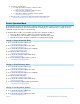
About Micro On/Off LED Sense #1 (yellow) Sense #2 (purple) Antenna Second Load Terminal optional based on region Features and Benefits - Wires in behind existing wall switch or outlet or in a fixture box (requires neutral wire) Compatible with latching, single momentary and dual momentary switches Sense wires allow local control from any standard wall switch Can contain up to 400 controller/responder links X10 compatible All settings preserved in non-volatile memory, even through power failures Beeper
Identifying the Electrical Wires in Your Home (North America only) - Line: usually black (may also be called hot, live or power), carries 120VAC electricity into the wall box Neutral: usually white or white wire bundle, commonly daisy-chained from box to box Load: usually black, from a separate cable jacket Ground: bare copper wire or metal fixture (if grounded) Identifying the Electrical Wires in Your Home (Europe/Australia/New Zealand) - As wire colors vary from country to country, make sure you always
Installation 1) 2) 3) Write down the INSTEON ID found on the back of the unit (XX.XX.XX) Turn off breaker/fuse and verify that the power is off Disconnect wires from existing switch, fixture or outlet and prep all wires to be connected to Micro module, with 3/16” (5mm) of bare wire on the ends 4) Connect wires per diagram which corresponds to your installation Note: sense lines carry very low current (~0.35mA 240V, ~0.
d) e) Perform the step that applies • For single momentary: slowly tap set button four times LED will continue blinking green • For dual momentary: slowly tap set button five times LED will start double-blinking green • To switch back to latching: slowly tap set button six times LED will start blinking green Once the mode is selected, press and hold set button until it double-beeps LED will stop blinking and turn green if load is on or red if load is off Switch Operation Mode By default, Micro module is
3) Press and hold Set button until it beeps a third time LED will start blinking green 4) Slowly tap Set button six times LED will continue blinking green 5) Press and hold Set button until it double-beeps LED will stop blinking 6) Test mode change by tapping switch on and off Load will respond appropriately 3-Way Toggle Mode (Latching Switches Only, Default) Because Micro module comes programmed for latching switches, 3-way toggle mode is enabled by default.
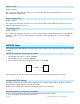
Single Momentary Switch Single momentary switch Switch Connected load/responders Tap Press and hold Double-tap LED On/Off Brighten/Dim On/Off (ramped) until release or full-on/off (dimmable responders only) (instant) Green/ Red Double-tap LED Dual Momentary Switch Dual momentary switch Connected load/responders Tap Press and hold On Brighten On (ramped) until release or 100% (dimmable responders only) (instant) Off Dim Off (ramped) until release or off (dimmable responders only) (
Blink on Traffic Default = disabled This setting is only adjustable via software or a central controller. Micro module LED will blink red if it detects noise that could disrupt communication. Beep on Button Press Default = disabled This setting is only adjustable via software or a central controller. Micro module will beep every time its connected switch is tapped or a button is pressed. Programming Lock Default = disabled This setting is only adjustable via software or a central controller.
Controller LED will start blinking You will have four minutes to complete the next steps before linking mode times out 2) Adjust load connected to Micro module to desired brightness level (even off) 3) Press and hold Micro module Set button until it double-beeps Controller will double-beep and its LED will stop blinking 4) Test link by tapping controller button on and off Load connected to Micro module will respond appropriately Make Micro Module a Responder (Switch) 1) Press and hold controller Set button
Groups Devices in a group share all the same settings (e.g., on-level, ramp rate). This keeps all group members synchronized. Every device in a group is both a controller of, and responder to, all the other devices. The most common example of a group is a 3-way lighting circuit (2 switches). For simplicity, we will assume that the desired group level is on.
Remove Micro Module as a Controller If you no longer want Micro module to control another device (or are removing Micro module from your network) it is important that you follow the instructions below for each responder.
6) After beep stops, release Micro module Set button After a few seconds, the LED will flash white Micro module will double-beep and the load will turn on X10 Setup Micro module ships with no X10 address assigned.
Specifications General Product name Micro On/Off Brand/manufacturer INSTEON 2443-222 (US) Manufacturer product number 2443-422 (EU) 2443-522 (AUS/NZ) 813922012736 (US) UPC 813922012743 (EU) 813922012750 (AUS/NZ) Warranty 2 years, limited INSTEON INSTEON Controller and responder Maximum links/scenes 400 Green when load is on, red when load is off Status LED Blinks red once when responder does not acknowledge/blinks green once if all responders acknowledge (can be disabled/re-enabled via softwa
2443-422 (869 MHz) 0x31 2443-522 (921 MHz) 0x32 X10 X10 address 1 optional (comes unassigned) X10 transmitter Yes X10 receiver Yes X10 status response Supported X10 resume dim Supported (by setting local on-level to zero) X10 minimum transmit level 3.
3600W/240VAC Resistive 700W/240VAC Inductive/Capacitive 2000W/240VAC Bulbs/Low Voltage Halogen Resistive Load type(s) Inductive/capacitive Low voltage halogen Hardwired remote control Yes, latching and momentary switches supported Retains all settings without power Yes, saved in non-volatile EEPROM Standby power consumption < 1 watt Safety approved ETL, CE, C-Tick FCC 15.107, 15.109, 15.
Troubleshooting Problem Possible Cause Solution Make sure the circuit breaker is turned on The LEDs on Micro Micro module is not getting module are not turning on power at all The switch I'm replacing only has two wires Check junction box wires to ensure all connections are tight and no bare wires are exposed Check the light fixture to ensure all connections are tight and no bare wires are exposed Look in the rear of the junction box for a group of wires tied together with a wire nut.
respond to X10 address A1 upon install Micro module is locked up an X10 Address A surge or excessive noise on the power line occurred Micro module supports an Micro module blinks green error blink feature.
Phase Bridge Detect Beacon/RF Range Test Micro module automatically bridges the electrical phases in your home (via communications with other dual-band devices on the “other phase”). This is only important in 2-phase homes with powerline-only INSTEON products or buildings with both 2- and 3- phase circuits. The phase bridge detect beacon can also be used as an RF range test to see if your devices are within communication range. You will need at least one other INSTEON dual-band device installed.
Certification and Warranty Certification This product has been thoroughly tested by ITS ETL SEMKO, a nationally recognized independent third-party testing laboratory. The North American ETL Listed mark signifies that the device has been tested to and has met the requirements of a widely recognized consensus of U.S.
liability with respect to this product. For repair or replacement during the warranty period, call INSTEON at 866-243-8022 with the Model # and Revision # of the device to receive an RMA# and send the product, along with all other required materials to: INSTEON ATTN: Receiving 16542 Millikan Ave.