ToggleLinc™ Relay INSTEON® Remote Control On/Off Switch Owner’s Manual (#2466Sxxx) Page 1 of 18 2466S - Rev: 1/21/2014 7:34 AM
ToggleLinc Relay – Features and Benefits............................................................................................... 3 Features..................................................................................................................................................... 3 What’s in the Box? ..................................................................................................................................... 4 Preparing to Install ToggleLinc ...........................
ToggleLinc Relay – Features and Benefits Congratulations on purchasing the high-quality INSTEON ToggleLinc Relay Switch. With its elegant look, smooth touch and stylish LED bar, you can not only control the lights you wire to it, but you can add remote control to all kinds of other INSTEON and X10 devices in your home to match your lifestyle. Besides controlling other devices, ToggleLinc itself can be remotely operated from other INSTEON controllers, including other ToggleLinc modules.
What’s in the Box? - ToggleLinc Relay Switch Quick Start Guide Two (2) mounting screws Four (4) wire nuts Preparing to Install ToggleLinc CAUTIONS AND WARNINGS Read and understand these instructions before installing and retain them for future reference. This product is intended for installation in accordance with the National Electric Code and local regulations in the United States or the Canadian Electrical Code and local regulations in Canada. Use indoors only.
) 6) 7) 8) 9) Ensure that all wire connectors are firmly attached and that there is no exposed copper except for the Ground wire. Orient ToggleLinc with the LED bar at the bottom, gently place it into the junction box and screw it into place. Enable power to the switch from the circuit breaker or fuse panel. Test that ToggleLinc is working properly by using the switch to turn the light on and off. Reinstall the faceplate.
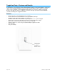
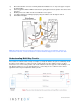
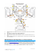
A wired-in 4- or more-way circuit (with three or more switches) has additional switches added in the middle of the circuit. In the diagram below, the additional switch (Switch 3+) is shown in two different positions, since wiring can vary from home to home. To learn more about multi-way circuits, go to your preferred Internet search engine and enter the search terms “3-way switch” or “4-way switch.
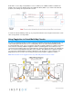
Fig. 1 • • • • Notice that the red Traveler wires are not used, so they are capped off at both ends with wire nuts. o The black Traveler wire (Traveler 2) is converted to a Line wire. o In the ToggleLinc Secondary’s junction box, connect Traveler 2 to the existing Line wire Fig. 2 and to the ToggleLinc Secondary’s Line wire. o In the junction box at the other end of the circuit, connect Traveler 2 to the ToggleLinc Primary’s Line wire.
13) 14) 15) 16) 17) 18) 19) 20) In the junction box where you will install ToggleLinc Primary, identify the Load wire (usually red). This is the wire that carries power from the switch to the load. Identify the black Traveler wire. If you are unsure, repeat steps 3-6 to measure the voltage and find the wire measuring 120VAC. This is the wire connected to the Line wire in step 7. Make sure the electricity is turned off before proceeding.
1) 2) 3) 4) 5) Connect ToggleLinc Secondary’s black Line wire to the junction box’s black Traveler wire with a wire nut. Cap the two unused Traveler wires (usually red) with wire nuts. Cap ToggleLinc Secondary’s red Load wire with a wire nut. Connect ToggleLinc Primary’s white Neutral wire to the box’s Neutral wires with a wire nut (see Fig. 3). Connect ToggleLinc Primary’s bare copper Ground wire to the junction box’s Ground wires with a wire nut (see Fig. 4). INSTEON Networks: Split Single-Phase vs.
Using ToggleLinc Relay Using the Toggle Like any traditional toggle switch, tapping the switch up turns on the load while down turns it off. Using the Air Gap Anytime you need ToggleLinc’s controlled circuit to be unpowered but don’t want to turn off the circuit breaker—such as when replacing light bulbs—use the air gap to quickly and conveniently disable power to the switch. Using your fingernail or a small flathead screwdriver, pull out ToggleLinc’s Set button as far as it will go (about 1/8”).
ToggleLinc will double-beep and its LED will stop blinking 4) Confirm that unlinking was successful by tapping ToggleLinc’s toggle on and off. The responder will no longer respond. Adding ToggleLinc Relay as an INSTEON Responder Follow the steps below to make ToggleLinc a responder of another INSTEON controller. 1) Press and hold the controller’s Set or scene button until it beeps and/or LED blinks (about 3 seconds).
Power Restore ToggleLinc Relay stores all of its scenes, properties, etc. in its internal non-volatile memory so all settings are retained after a power outage. Upon power being restored, ToggleLinc will return its connected load(s) and all LEDs to their states prior to power outage. Programming ToggleLinc Relay as Part of an X10 Network Like most INSTEON devices, ToggleLinc Relay is X10-ready, meaning it can both send and respond to X10 commands.
2) Tap ToggleLinc’s Set button. ToggleLinc status LED will double-blink. You will have 4 minutes to complete the next step before multi-linking mode times out. 3) For each responder you are adding: a. Tap on/off or press and hold to adjust responder to desired state. b. Press and hold responder Set button until it beeps (or LED flashes). ToggleLinc will double-beep. 4) After all responders have been added, tap ToggleLinc Set button. ToggleLinc LED will stop blinking.
Changing LED Brightness Levels ToggleLinc Relay’s status LED can be adjusted to shine brighter or dimmer, or even turned off. 1) Press and hold Set button until it beeps. ToggleLinc’s status LED will blink. 2) Press and hold Set button until it beeps again. ToggleLinc’s status LED will continue blinking. 3) Press and hold Set button until it beeps a third time. ToggleLinc’s status LED will stop blinking. 4) Press and hold the toggle up or down to brighten/dim the status LED to the desired level.
Warranty Two years, limited Operation LED 1 dimmable white status LED Operation Modes INSTEON only, X10 only, INSTEON and X10 combo Combo Mode Message Order INSTEON, INSTEON cleanup, X10 Multi-Way Circuit Support One ToggleLinc Relay controls load, Cross-Link any number of ToggleLinc Relays or other INSTEON Controllers Setup Memory Non-volatile EEPROM INSTEON INSTEON Address 1 hard-coded out of 16,777,216 possible Maximum Scene Memberships 417 INSTEON Powerline Frequency 131.
X10 Controllable Addresses 1 same address as primary address X10 Status Response Supported X10 Powerline Frequency 120KHz X10 Minimum Transmit Level 3.2 Vpp into 5 Ohms X10 Minimum Receive Level 20mV into 5 Ohms X10 Messages Repeated No Troubleshooting Problem Possible Cause Solution Make sure the circuit breaker is turned on. The LED on ToggleLinc is not turning on at all and ToggleLinc won't control my light. Make sure the Set button is not pulled out (air gap).
controller. interfering with the reception of powerline signal. Install additional INSTEON devices to boost the INSTEON signal. Increase the X10 signal strength with an INSTEON-compatible X10 booster to overcome the power line noise. Remove the X10 address from the button on your INSTEON controller so it doesn’t send both INSTEON and X10 commands. When I press the toggle on ToggleLinc, it takes a long time for other INSTEON responders to respond.
Certification and Warranty Certification This product has been thoroughly tested by ITS ETL SEMKO, a nationally recognized independent third-party testing laboratory. The North American ETL Listed mark signifies that the device has been tested to and has met the requirements of a widely recognized consensus of U.S.