KeypadLinc Schedule Timer INSTEON® Keypad Schedule Timer Model : 2484DST6 (Dimmer) 2485S (On/Off Switch)
KeypadLinc Schedule Timer Owner’s Manual TABLE OF CONTENTS ABOUT KEYPADLINC SCHEDULE TIMER .................................................................................................................3 Key KeypadLinc Schedule Timer Features ................................................................................................................3 What is Included with KeypadLinc Schedule Timer....................................................................................................
KeypadLinc Schedule Timer Owner’s Manual ABOUT KEYPADLINC SCHEDULE TIMER KeypadLinc Schedule Timer presents you with an elegant and stylish way to control a wired-in light and add timer capabilities to your existing INSTEON devices. Use the buttons on KeypadLinc to create and control customized lighting “scenes” within your home. Or send commands from another INSTEON device and you’ll be able to conveniently and remotely control KeypadLinc.
KeypadLinc Schedule Timer Owner’s Manual What is Included with KeypadLinc Schedule Timer • 1x - KeypadLinc Schedule Timer – INSTEON Keypad Schedule Timer with Dimmer or On/Off Switch • 2x - Mounting screws • 4x - Wire nuts • 1x - Quick-Start Guide WHAT IS INSTEON? Since its inception in 2005, INSTEON has become a best-selling home-control networking technology, offering more reliability and flexibility than any other home management system on the market.
KeypadLinc Schedule Timer Owner’s Manual • Be sure that you have turned off the circuit breaker or removed the fuse for the circuit you are installing KeypadLinc in. Installing KeypadLinc with the power on will expose you to dangerous voltages. • Connect only copper or copper-clad wire to KeypadLinc • KeypadLinc may feel warm during operation. The amount of heat generated is within approved limits and poses no hazards.
KeypadLinc Schedule Timer Owner’s Manual Installing KeypadLinc Schedule Timer 1) At the circuit breaker or fuse panel, disconnect the power for all of the circuits in the switch junction box. Verify that the power is off by trying to turn on the lights controlled by the switches. 2) Remove the wallplate from the switch you are replacing. Then, unscrew the switch itself and pull it out from the junction box. 3) Disconnect the wires from the switch you are replacing.
KeypadLinc Schedule Timer Owner’s Manual Installing KeypadLinc Schedule Timer in a Multi-Way Circuit Understanding Multi-Way Circuits If more than one switch controls a single set of lights (called a load), the switches are part of a multi-way circuit. A 3-way circuit uses two switches to control a load, a 4-way circuit uses three switches, and so forth. Most homes have one or more 3-way circuits, with two switches located in hallways, stairwells, or two different entrances to a room.
KeypadLinc Schedule Timer Owner’s Manual Using KeypadLinc Schedule Timer in Virtual Multi-Way Circuits Once KeypadLincs have been installed, you can create a virtual multi-way circuit to control a single load. Rather than connect each switch directly to the load, virtual multi-ways use INSTEON messaging to control the load.
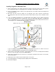
KeypadLinc Schedule Timer Owner’s Manual Step-by-Step Instructions for Installing Multi-Way KeypadLincs When replacing a 3-way mechanical switch, each switch will have three wires connected to it from the wall box. Four-way or greater circuits will have four wires connected to the switches in the center of the circuit. For this tutorial, we will follow the most commonly used wire colors for homes in North America. 1) Find the LINE wire.
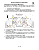
KeypadLinc Schedule Timer Owner’s Manual 6) Connect the KeypadLinc Secondary’s GROUND Wire. Connect the bare copper GROUND wire to the other GROUND wire in the junction box. 7) Install additional KeypadLinc Secondaries. If you have a 4-way or greater switching circuit, see Special Treatment for 4- or More-Way Circuits at the end of this section. 8) Identify the wires for the KeypadLinc Primary. The KeypadLinc Primary is the KeypadLinc that will actually control the load.
KeypadLinc Schedule Timer Owner’s Manual Special Treatment for 4- or More-Way Circuits If your lighting circuit includes more than two switches controlling a single set of lights, those extra switches will have four wires connected to them. Two of the wires are TRAVELERS from the preceding switch and the other two are TRAVELERS to the next switch in the chain. You will be converting the black TRAVELER wires to the LINE wires and replacing the old 4-wire switches with KeypadLinc Secondaries.
KeypadLinc Schedule Timer Owner’s Manual USING KEYPADLINC SCHEDULE TIMER Using the Buttons to Control Scenes On/Off Buttons The load (device wired-in to KeypadLinc) can be controlled by using the dedicated On/Off buttons. If you wish to include the load in a scene, you must use the dedicated On/Off buttons. Scene Buttons The A, B, C, and D buttons are considered “Scene buttons”, meaning you can use any of the buttons on KeypadLinc to create INSTEON scenes.
KeypadLinc Schedule Timer Owner’s Manual Setting the Clock in KeypadLinc Schedule Timer 1) Set KeypadLinc to Programming Mode by pressing & holding the Set button for 3 seconds The LED will cycle between the On, A, and B buttons 2) Tap the A button to enter Clock Setup Mode KeypadLinc will beep and the On button will begin blinking (if the clock has already been programmed, KeypadLinc will flash the A, B, C, and D buttons to show the clock time) 3) Once the On button begins blinking continuously, tap the A,
KeypadLinc Schedule Timer Owner’s Manual Using the Air Gap 1 Pulling the Set button at the bottom of the paddle out as far as it will go (about /8 inch) opens mechanical contacts that remove all power from KeypadLinc and the load that it controls. “Air gapping” can be useful for replacing bulbs or any other time you want the controlled circuit to be unpowered. Because the KeypadLinc settings are stored in non-volatile memory, setup information will not be lost when the device unpowered.
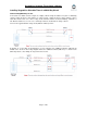
KeypadLinc Schedule Timer Owner’s Manual Setting the Ramp Rate on KeypadLinc Dimmer NOTE: Setting the Ramp Rate does not change/affect the On-Level brightness. 1) Setting the Ramp Rate is done using the brightness level as an indicator for how fast KeypadLinc should ramp. Use the On and Off buttons on KeypadLinc to set the brightness to a brighter level for a faster Ramp Rate or dimmer for a slower Ramp Rate. 100% bright corresponds to a 0.
KeypadLinc Schedule Timer Owner’s Manual CONTROLLING INSTEON RESPONDERS FROM KEYPADLINC SCHEDULE TIMER Linking KeypadLinc Schedule Timer to an INSTEON Responder To use KeypadLinc as an INSTEON Controller, follow these steps to Link KeypadLinc and an INSTEON Responder (the device you wish to control with KeypadLinc) together. Refer to the Responder’s Owner’s Manual for detailed instructions on how to properly install and Link it to KeypadLinc.
KeypadLinc Schedule Timer Owner’s Manual CONTROLLING KEYPADLINC SCHEDULE TIMER FROM AN INSTEON CONTROLER Linking an INSTEON Controller to KeypadLinc Schedule Timer To use KeypadLinc as an INSTEON Responder, follow these steps to Link KeypadLinc and a Controller together. Refer to the Controller’s Owner’s Manual for detailed instructions on how to properly install and Link it to KeypadLinc.
KeypadLinc Schedule Timer Owner’s Manual ADVANCED FEATURES Multi-Linking and Multi-Unlinking Multi-Linking Multi-Linking Mode allows you to Link multiple Responders to a single Controller and quickly create an INSTEON scene. Once the Controller is in Multi-Linking Mode, you can Link any number of Responders, one right after the other.
KeypadLinc Schedule Timer Owner’s Manual Cross-Linking INSTEON Devices Cross-Linking Two INSTEON Devices Cross-Linking devices allow you to track the on/off status of the load on all Linked INSTEON Responders. For this example we will use a primary device controlling the load and one secondary device in a virtual 3-way. They will be referred to as: the Primary Device (the device wired to the load or load-controlling) and the Secondary Device (the additional device in the circuit).
KeypadLinc Schedule Timer Owner’s Manual Viewing/Editing a Scene’s On/Off Timers 1) Set KeypadLinc to Programming Mode by pressing & holding the Set button for 3 seconds The LED will cycle between the On, A, and B buttons 2) Tap the B button to enter Timer Setup Mode KeypadLinc will beep and the LED will cycle between the On, A, B, C, and D buttons 3) Tap the Scene button you wish to view/edit timers for KeypadLinc will beep and the LED will cycle between the On and Off buttons 4) Tap either the On or Off b
KeypadLinc Schedule Timer Owner’s Manual Resetting KeypadLinc Schedule Timer to its Factory Default Settings The factory reset procedure can be used to clear the KeypadLinc memory of all INSTEON Links, timers, programmed On-Levels and Ramp Rates, X10 addresses, etc. 1) If you are using a Controller to control KeypadLinc, be sure to Unlink it from the Controller. See Unlinking KeypadLinc Schedule Timer from an INSTEON Controller.
KeypadLinc Schedule Timer Owner’s Manual ABOUT INSTEON Using Dual-Band INSTEON Devices to Upgrade Your Network What are phases? The majority of single-family homes in North America have two phases (or “legs”) of 110 Volts coming into their electricity panels. From the panel, they are distributed throughout the home, providing power to outlets and wall switches. These phases come together in some parts of the home to provide 220 Volts of power to large appliances, such as an electric oven or pool pump.
KeypadLinc Schedule Timer Owner’s Manual TROUBLESHOOTING Problem Possible Cause Solution Make sure the circuit breaker is turned on. The LEDs on KeypadLinc are not turning on and won’t control the load. Make sure the air gap (Set button) is not pulled out. KeypadLinc may not be getting power. Check the junction box wires to ensure all connections are tight and no bare wires are exposed. Check the light fixture to ensure all connections are tight and no bare wires are exposed.
KeypadLinc Schedule Timer Owner’s Manual Problem The load turned on by itself. Possible Cause Another Controller, a timer, or stray X10 signals could have triggered KeypadLinc. Solution Perform a factory reset. See Resetting KeypadLinc Schedule Timer to its Factory Default Settings. KeypadLinc can turn off a Responder, but The Responder may be nothing happens when I Linked at its off state. send an ON command from KeypadLinc. Re-Link the Responder to KeypadLinc, while the Responder’s load is on.
KeypadLinc Schedule Timer Owner’s Manual Problem KeypadLinc trips the Arc Fault Circuit Interrupter (AFCI). Possible Cause The AFCI might be too sensitive. Solution Replace the AFCI with a less sensitive brand or model from a hardware store with a customer-friendly return policy.
KeypadLinc Schedule Timer Owner’s Manual Limited Warranty Seller warrants to the original consumer purchaser of this product that, for a period of two years from the date of purchase, this product will be free from defects in material and workmanship and will perform in substantial conformity to the description of the product in this Owner’s Manual. This warranty shall not apply to defects or errors caused by misuse or neglect.