ToggleLinc™ Dimmer INSTEON® Remote Control Dimmer Switch Owner’s Manual (#2466Dxxx) Page 1 of 20 2466D - Rev: 1/21/2014 7:34 AM
ToggleLinc Dimmer – Features and Benefits ........................................................................................... 3 Features..................................................................................................................................................... 3 What’s in the Box? ..................................................................................................................................... 4 Preparing to Install ToggleLinc .............................
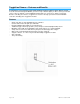
ToggleLinc Dimmer – Features and Benefits Congratulations on purchasing the high-quality INSTEON ToggleLinc Dimmer Switch. With its elegant look, smooth touch and stylish LED bar, you can not only control the lights you wire to it, but you can add remote control to all kinds of other INSTEON and X10 devices in your home to match your lifestyle. Besides controlling other devices, ToggleLinc itself can be remotely operated from other INSTEON controllers, including other ToggleLinc modules.
What’s in the Box? - ToggleLinc Dimmer Switch Quick Start Guide Two (2) mounting screws Four (4) wire nuts Preparing to Install ToggleLinc CAUTIONS AND WARNINGS Read and understand these instructions before installing and retain them for future reference. This product is intended for installation in accordance with the National Electric Code and local regulations in the United States or the Canadian Electrical Code and local regulations in Canada. Use indoors only.
) 6) 7) 8) 9) Ensure that all wire connectors are firmly attached and that there is no exposed copper except for the Ground wire. Orient ToggleLinc with the LED bar at the bottom, gently place it into the junction box and screw it into place. Enable power to the switch from the circuit breaker or fuse panel. Test that ToggleLinc is working properly by using the switch to turn the light on and off. Reinstall the faceplate.
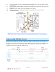
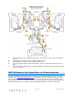
A wired-in 4- or more-way circuit (with three or more switches) has additional switches added in the middle of the circuit. In the diagram below, the additional switch (Switch 3+) is shown in two different positions, since wiring can vary from home to home. To learn more about multi-way circuits, go to your preferred Internet search engine and enter the search terms “3-way switch” or “4-way switch.
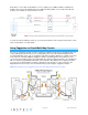
Fig. 1 • • • • Notice that the red Traveler wires are not used, so they are capped off at both ends with wire nuts. o The black Traveler wire (Traveler 2) is converted to a Line wire. o In the ToggleLinc Secondary’s junction box, connect Traveler 2 to the existing Line wire Fig. 2 and to the ToggleLinc Secondary’s Line wire. o In the junction box at the other end of the circuit, connect Traveler 2 to the ToggleLinc Primary’s Line wire.
13) 14) 15) 16) 17) 18) 19) 20) In the junction box where you will install ToggleLinc Primary, identify the Load wire (usually red). This is the wire that carries power from the switch to the load. Identify the black Traveler wire. If you are unsure, repeat steps 3-6 to measure the voltage and find the wire measuring 120VAC. This is the wire connected to the Line wire in step 7. Make sure the electricity is turned off before proceeding.
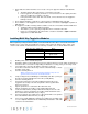
1) 2) 3) 4) 5) Connect ToggleLinc Secondary’s black Line wire to the junction box’s black Traveler wire with a wire nut. Cap the two unused Traveler wires (usually red) with wire nuts. Cap ToggleLinc Secondary’s red Load wire with a wire nut. Connect ToggleLinc Primary’s white Neutral wire to the box’s Neutral wires with a wire nut (see Fig. 3). Connect ToggleLinc Primary’s bare copper Ground wire to the junction box’s Ground wires with a wire nut (see Fig. 4). INSTEON Networks: Split Single-Phase vs.
Using ToggleLinc Dimmer Using the Toggle Like any traditional toggle switch, tapping the switch up turns on the load while down turns it off. The load’s behavior changes depending on whether you tap, double-tap or press and hold the toggle.
52-61% 2 39-48% 2 26-35% 4.5 13-23% 6.5 1-10% 8.5 0% 9 2) Once the brightness level has been reached, double-tap ToggleLinc’s Set button. ToggleLinc will beep. 4) Test the local ramp rate by tapping ToggleLinc’s toggle up and down. 3) The load connected to ToggleLinc will ramp on and off at the set rate. 4) Note: when using HouseLinc or other home-management software, you can set local on-levels and ramp rates consistently for multiple devices throughout your home.
Status LED will continue blinking. You will have 4 minutes to complete the next step before unlinking mode times out. 3) Press and hold the responder’s Set button for 3 seconds. ToggleLinc will double-beep and its LED will stop blinking 4) Confirm that unlinking was successful by tapping ToggleLinc’s toggle on and off. The responder will no longer respond. Adding ToggleLinc Dimmer as an INSTEON Responder Follow the steps below to make ToggleLinc a responder of another INSTEON controller.
Power Restore ToggleLinc Dimmer stores all of its scenes, properties, etc. in its internal non-volatile memory so all settings are retained after a power outage. Upon power being restored, ToggleLinc will return its connected load(s) and all LEDs to their states prior to power outage. Programming ToggleLinc Dimmer as Part of an X10 Network Like most INSTEON devices, ToggleLinc Dimmer is X10-ready, meaning it can both send and respond to X10 commands.
2) Tap ToggleLinc’s Set button. ToggleLinc status LED will double-blink. You will have 4 minutes to complete the next step before multi-linking mode times out. 3) For each responder you are adding: a. Tap on/off or press and hold to adjust responder to desired state. b. Press and hold responder Set button until it beeps (or LED flashes). ToggleLinc will double-beep. 4) After all responders have been added, tap ToggleLinc Set button. ToggleLinc LED will stop blinking.
Changing LED Brightness Levels ToggleLinc Dimmer’s status LED can be adjusted to shine brighter or dimmer, or even turned off. 1) Press and hold Set button until it beeps. ToggleLinc’s status LED will blink. 2) Press and hold Set button until it beeps again. ToggleLinc’s status LED will continue blinking. 3) Press and hold Set button until it beeps a third time. ToggleLinc’s status LED will stop blinking. 4) Press and hold the toggle up or down to brighten/dim the status LED to the desired level.
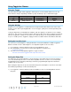
Warranty Two years, limited Operation On-Levels 32 locally; increments of 1% with software Ramp Rate 0.1 to 9 seconds if programmed locally; 0.
Operating Humidity Range Up to 85% relative humidity Electrical Voltage 120 volts AC +/- 10%, 60 Hertz, single phase Power Wire Leads 6", 16 AWG, stranded, 600V, 105°C insulation, ends stripped and tinned, Line (black), Load (red), Neutral (white) Ground Lead 6”, 18 AWG, stranded, bare copper Load Type(s) Wired-in incandescent lighting devices Maximum Load 600W Standby power consumption 1.
device. ToggleLinc doesn't always respond to an INSTEON controller. The light turned on by itself. Make sure you are not experiencing interference with older X10 BoosterLinc technology. Upgrade to INSTEON-compatible BoosterLinc modules (#4827). The INSTEON controller may have been reset without first unlinking ToggleLinc from it. Another controller, a timer or stray X10 signals triggered ToggleLinc. Relink ToggleLinc to the INSTEON controller. See Adding ToggleLinc as an INSTEON Responder.
reset. See Factory Reset. ToggleLinc is getting warm to the touch. ToggleLinc Dimmer will dissipate about 1W per It is normal for wall dimmers to 100W controlled. Using metal junction boxes, feel warm, but not hot. removing insulation around the box or controlling a smaller load can lessen the heat. ToggleLinc can turn off my responder, but nothing happens when I send an ON command from ToggleLinc. Your responder may be linked Relink your responder to ToggleLinc, while the at its off state.
Certification and Warranty Certification This product has been thoroughly tested by ITS ETL SEMKO, a nationally recognized independent third-party testing laboratory. The North American ETL Listed mark signifies that the device has been tested to and has met the requirements of a widely recognized consensus of U.S.