SwitchLinc™ Dimmer High Wattage INSTEON® Dual-Band Remote Control Dimmer Owner’s Manual (rev 7.
The Basics ................................................................................................................................................... 3 Cautions and Warnings .............................................................................................................................. 3 Identifying the Electrical Wires in Your Home ........................................................................................... 3 Installation ...............................................
The Basics In the Box SwitchLinc Dimmer High Wattage Quick Start Guide 2 screws and 4 wire nuts Tools Needed Flathead and Phillips screwdrivers Wire cutter/stripper Voltage meter Optional Accessories INSTEON app SmartLinc Hub Cautions and Warnings Read and understand these instructions before installing and retain them for future reference.
7) 8) Turn off power Connect wires as per table/diagram (confirm firm attachments with no exposed wire) If you are installing SwitchLinc in a multi-gang box next to another switch, you may need to remove one or both pairs of metal heatsink tabs on the back of SwitchLinc. Note that removing a pair of tabs will derate SwitchLinc from 1000W to 800W (one pair removed) or 600W (both pairs removed).
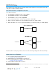
13) 14) 15) 16) 17) 18) Connect SwitchLinc white wire to neutral wire(s) in wall box (usually white) Connect SwitchLinc red wire to load wire Connect SwitchLinc black wire to same color traveler from Box 1 carrying Line (usually black) Cap unused traveler wire With LEDs on left, gently place SwitchLincs into their wall boxes and screw in place Turn power back on SwitchLincs and connected load will turn on (only SwitchLinc in Box 2 will operate load) 19) Add both SwitchLincs to a group.
In Box 2 (Traveler box) 12) Connect SwitchLinc bare wire to ground 1 13) Connect SwitchLinc white wire to neutral 14) Cap SwitchLinc red wire 15) Connect SwitchLinc black wire to same color traveler from Box 1 that you connected to line along with same color traveler wires leading to Box 3 16) Cap the last unused traveler wire(s) In Box 3 (Load box) 17) Connect SwitchLinc bare wire to ground 18) Connect SwitchLinc white wire to neutral 19) Connect SwitchLinc red wire to load 20) Connect SwitchLinc black wir
INSTEON Setup Some products have subtle differences in their setup procedures. Where necessary, please refer to the other device’s owner’s manual for details. INSTEON Controllers, Responders and Links Let’s define a few terms.
SwitchLinc will turn on (at desired brightness) and off Make SwitchLinc a Controller 1) 2) 3) 4) 5) Press and hold SwitchLinc Set button until it beeps LED will start blinking green Adjust responder to desired brightness/state Press and hold responder Set button until it double-beeps SwitchLinc will double-beep and its LED will stop blinking Test by tapping SwitchLinc paddle on and off Responder will turn on (at desired brightness) and off To add more responders, repeat steps 1-4 for each responder Group
7) Test by tapping controller button on and off SwitchLinc and all scene responders will turn on (to desired brightness/states) and off Remove SwitchLinc as a Controller (Unlink) 1) Press and hold SwitchLinc Set button until it beeps LED will start blinking green 2) Press and hold SwitchLinc Set button until it beeps LED will start blinking red 3) Press and hold responder Set button until it double-beeps SwitchLinc will double-beep and its LED will stop blinking 4) Test by tapping SwitchLinc on and off For
4) When long beep stops, release Set button A few seconds will pass SwitchLinc will double-beep The connected load will turn on X10 Setup SwitchLinc ships with no X10 address assigned. Add X10 Address 1) Turn SwitchLinc on. 2) Press and hold Set button until it beeps.
2) Tap Set button SwitchLinc will beep 3) Test: a. Brighten SwitchLinc to a random brightness level (e.g. 75%) b. Turn SwitchLinc off c. Turn SwitchLinc back on Light will turn on at the defined brightness level Local Ramp Rate Default = ½ second. The local ramp rate is the time it takes for SwitchLinc to reach 100% brightness (from off) when controlled at the paddle. It is adjustable from instant to 8 minutes (with software) and instant to 5 seconds (using Set button).
Error Blink Default = on. This setting is adjustable via software or a central controller only. SwitchLinc LED blinks for a few seconds if one or more responders do not acknowledge a message.
X10 status response Supported X10 resume dim Supported (by setting local on-level to zero) X10 minimum transmit level 3.2 Vpp into 5 Ohms X10 minimum receive level Mechanical 20mV into 5 Ohms Case color Mounts in single or multiple-ganged junction box. Control 200W less load for each immediately adjacent SwitchLinc Dimmer installed. For example, 600 W load control becomes 400 W with another dimmer to the immediate right or left.
The switch I'm replacing only has two wires SwitchLinc is able to communicate with another INSTEON device SwitchLinc needs a neutral wire in order to operate SwitchLinc and the other device are out of range The other device is near a localized powerline noise source or attenuator The light turned on by itself Another controller, a timer or a stray X10 signal was received It takes a long time for one or more of SwitchLinc’s responders to respond SwitchLinc is repeatedly retrying to control a missing r
Certification and Warranty Certification This product has been thoroughly tested by ITS ETL SEMKO, a nationally recognized independent third-party testing laboratory. The North American ETL Listed mark signifies that the device has been tested to and has met the requirements of a widely recognized consensus of U.S.