
user manual


Page 7 of 15 Rev: 1/21/2014 7:29 AM
INSTEON Setup
Some products have subtle differences in their setup procedures. Where necessary, please refer to the
other device’s owner’s manual for details.
INSTEON Controllers, Responders and Links
Let’s define a few terms.
• Each INSTEON compatible product is called a device
• The INSTEON “transmitter” is called a controller
• The INSTEON “receiver” is called a responder
• The association between the controller and responder is called a link
• When a controller simultaneously controls multiple responders, it is called a scene
• When all members of a scene are synchronized (always go on and off together), it is called a group
Note that a link is one way. If you wish to have control “the other way,” simply add a link “the other way.”
Make SwitchLinc a Responder
1) Press and hold controller button until it beeps
Controller LED will start blinking
2) Adjust SwitchLinc to desired brightness for link/scene
1
3) Press and hold SwitchLinc Set button until it double-beeps
Controller LED will stop blinking
4) Test by tapping controller button on and off
1
If the responder is a multi-scene device such as a KeypadLinc, tap the scene button you wish to control until its LED is in the desired scene state (on or off). You can program
any state, not just on, for the responder’s link.
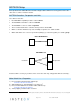
Controller
Links
INSTEON Scene
Controller
Responder
Link
Basic INSTEON Link
Responders