OutletLinc ™ INSTEON® Remote Control Outlet Model : 2473S
OutletLinc Owner’s Manual TABLE OF CONTENTS ABOUT OUTLETLINC.................................................................................................................................. 3 Key OutletLinc Features ............................................................................................................................ 3 What is Included with OutletLinc ............................................................................................................... 3 WHAT IS INSTEON?.....
OutletLinc Owner’s Manual ABOUT OUTLETLINC OutletLinc presents you with an elegant, stylish, and unobtrusive way to add remote control capabilities to any plug-in devices or appliances.
OutletLinc Owner’s Manual WHAT IS INSTEON? Since its inception in 2005, INSTEON has become a best-selling home-control networking technology, offering more reliability and flexibility than any other home management system on the market. INSTEON systems are simple, reliable, and affordable. Simple, because each device takes mere minutes to install. Reliable, because every INSTEON device works as a network repeater, ensuring your commands will not be lost.
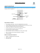
OutletLinc Owner’s Manual Preparing to Install OutletLinc CAUTION Read and understand these instructions before installing and retain them for future reference. OutletLinc is intended for installation in accordance with the National Electric Code and local regulations in the United States or the Canadian Electrical Code and local regulations in Canada. Use indoors only. OutletLinc is not designed nor approved for use on power lines other than 120V 60Hz, single phase.
OutletLinc Owner’s Manual Identifying the Electrical Wires in your Home To install OutletLinc, you will need to identify the following four wires: • LINE - usually black, may also be called HOT or LIVE, carries electricity into the switch • LOAD - usually black, red, or blue, carries electricity away from the switch and to the load • NEUTRAL - usually white, may not previously be connected to outlets • GROUND - bare copper wire You can usually identify the wires based on color.
OutletLinc Owner’s Manual CONTROLLING OUTLETLINC FROM AN INSTEON CONTROLLER Linking an INSTEON Controller to OutletLinc To use OutletLinc as an INSTEON Responder, follow these steps to Link OutletLinc and a Controller together. Refer to the Controller’s Owner’s Manual for detailed instructions on how to properly install and Link it to OutletLinc. The following will work for the most common INSTEON devices: 1) Set the Controller to Linking Mode.
OutletLinc Owner’s Manual ADVANCED FEATURES Enabling / Disabling Load Sensing Load Sensing allows you to manually turn on the load plugged into OutletLinc by using the switch on the load itself, without sending a command from an INSTEON or X10 controller. When the load is in the off state (with Load Sensing enabled), OutletLinc will “sense” that you are trying to turn it on with its built-in switch. When OutletLinc senses this, it will turn on the load automatically.
OutletLinc Owner’s Manual Restoring Power to OutletLinc OutletLinc stores all of its settings, such as Links to other INSTEON devices, On-Levels/Ramp Rates, etc., with non-volatile memory. Because settings are saved in this non-volatile memory, they will not be lost in the event of a power failure. In the event of a power loss OutletLinc will automatically return the load to the brightness level it had before power was interrupted.
OutletLinc Owner’s Manual X10 PROGRAMMING OPTIONS OutletLinc is X10 ready, meaning that it can respond to X10 commands from X10 controllers. However, to operate OutletLinc in X10 mode, you must first set up an X10 address. As it ships from the factory or after a factory reset procedure, OutletLinc will have not have an X10 address set up.
OutletLinc Owner’s Manual About X10 Scene Address Programming OutletLinc can be a member of up to 255 X10 scenes. An X10 scene address is just another X10 address like the X10 Primary Address. When an X10 command is sent to an X10 scene address, every X10 device with that address will turn on to its independent On-Level at its independent Ramp Rate (if a dimmable device).
OutletLinc Owner’s Manual ABOUT INSTEON Using Dual-Band INSTEON Devices to Upgrade Your Network What are phases? The majority of single-family homes in North America have two phases (or “legs”) of 110 Volts coming into their electricity panels. From the panel, they are distributed throughout the home, providing power to outlets and wall switches. These phases come together in some parts of the home to provide 220 Volts of power to large appliances, such as an electric oven or pool pump.
OutletLinc Owner’s Manual TROUBLESHOOTING Problem Possible Cause The Status LED on OutletLinc may not be getting OutletLinc is not turning on power. and won’t control the load. OutletLinc won’t Link or work with a Controller. OutletLinc is taking a long time to respond to a Controller. Solution Make sure the circuit breaker is turned on. Check the junction box wires to ensure all connections are tight and no bare wires are exposed. The Controller might have been reset without OutletLinc from it.
OutletLinc Owner’s Manual SPECIFICATIONS, CERTIFICATION, AND WARRANTY Specifications View specifications for OutletLinc at: www.smarthome.com/2473SWH.html Certification This product has been thoroughly tested by ITS ETL SEMKO, a nationally recognized independent third-party testing laboratory. The North American ETL Listed mark signifies that the device has been tested to and has met the requirements of a widely recognized consensus of U.S.