SwitchLinc™ Dimmer INSTEON® Remote Control Dimmer Switch Owner’s Manual (rev 5.
SwitchLinc Dimmer – Features and Benefits ........................................................................................... 3 Features..................................................................................................................................................... 3 What’s in the Box? ..................................................................................................................................... 4 Installing SwitchLinc .......................................
SwitchLinc Dimmer – Features and Benefits Congratulations on purchasing the high-quality INSTEON SwitchLinc Dimmer Switch. With its elegant look, smooth touch and stylish LED bar, you can not only control the lights you wire to it, but you can add remote control to all kinds of other INSTEON and X10 devices in your home to match your lifestyle. Besides controlling other devices, SwitchLinc itself can be remotely operated from other INSTEON controllers, including other SwitchLinc modules.
What’s in the Box? - SwitchLinc Dimmer Quick Start Guide Two (2) mounting screws Four (4) wire nuts Installing SwitchLinc CAUTIONS AND WARNINGS Read and understand these instructions before installing and retain them for future reference. This product is intended for installation in accordance with the National Electric Code and local regulations in the United States or the Canadian Electrical Code and local regulations in Canada. Use indoors only.
) 6) 7) 8) 9) Ensure that all wire connectors are firmly attached and that there is no exposed copper except for the ground wire Orient SwitchLinc with the LED bar at the left, gently place it into the wall box and screw it into place Enable power to the switch from the circuit breaker or fuse panel Test that SwitchLinc is working properly by using the paddle to turn the light on and off Reinstall the faceplate Note: the neutral wire will not normally be connected to the switch you are replacing.
A wired-in 4- or more-way circuit (with three or more switches) has additional switches added in the middle of the circuit. In the diagram below, the additional switch (Switch 3+) is shown in two different positions, since wiring can vary from home to home. To learn more about multi-way circuits, go to your preferred Internet search engine and enter the search terms “3-way switch” or “4-way switch.
• • • • Notice that the red traveler wires are not used, so they are capped off at both ends with wire nuts o The black traveler wire (traveler 2) is converted to a line wire o In SwitchLinc Secondary wall box, connect traveler 2 to the existing line wire and to SwitchLinc Secondary line wire o In the wall box at the other end of the circuit, connect traveler 2 to SwitchLinc Primary line wire The SwitchLinc Primary load wire is connected to the actual lights being controlled The load wires on all SwitchLi
13) 14) 15) 16) 17) 18) 19) 20) In the wall box where you will install SwitchLinc Primary, identify the load wire (usually red). This is the wire that carries power from the switch to the load. Identify the black traveler wire. If you are unsure, repeat steps 3-6 to measure the voltage and find the wire measuring 120VAC. This is the wire connected to the line wire in step 7.
1) 2) 3) 4) 5) Connect SwitchLinc Secondary black line wire to the wall box black traveler wire with a wire nut Cap the two unused traveler wires (usually red) with wire nuts Cap SwitchLinc Secondary red load wire with a wire nut Connect SwitchLinc Primary white neutral wire to the box neutral wires with a wire nut (see Fig. 3) Connect SwitchLinc Primary bare copper ground wire to the wall box ground wires with a wire nut (see Fig.
Ramp Rate The local ramp rate is the time it takes for SwitchLinc to reach 100% brightness (from off) when controlled at the paddle. The default ramp rate is 0.5 seconds, but it is adjustable from instant-on to 9 seconds (using Set button) or up to 8 minutes (with software). The ramp rate is set up using the light’s brightness level as the indicator for the ramping speed: the brighter the light, the faster the ramp rate.
Make SwitchLinc a Controller Follow the steps below to link SwitchLinc as a controller of another INSTEON device. 1) Press and hold SwitchLinc Set button until it beeps (about 3 seconds) Status LED will blink green You will have 4 minutes to complete the next steps before linking mode times out 2) Set the responder to the state you want to activate from SwitchLinc (e.g.
1) Press and hold the controller Set or scene button until it beeps and/or LED blinks (about 3 seconds) Controller LED will blink 2) Press and hold the controller Set or scene button until it beeps and/or LED blinks again Controller LED will continue blinking You will have 4 minutes to complete the next step before unlinking mode times out 3) Press and hold SwitchLinc Set button until it double-beeps SwitchLinc status LED will flash once, then turn on solid 4) Confirm that unlinking was successful by tappin
SwitchLinc status LED will blink 2) Press and hold SwitchLinc Set button until it beeps again SwitchLinc status LED will continue blinking You will have 4 minutes to complete the next step before unlinking mode times out 3) Using an X10 controller, send the X10 address you want to remove followed by the ON command three times For example, to remove the address A1, you would send A1-ON-A1-ON-A1-ON 4) Once SwitchLinc has received the sequence, it will exit unlinking mode SwitchLinc will beep.
1) Link SwitchLinc as a controller of another INSTEON device. (See Make SwitchLinc a Controller.) 2) Link the same INSTEON device as a controller of SwitchLinc. (See Make SwitchLinc a Responder.
Change Paddle and LED Colors You can swap out the included white LEDs and/or front paddle and trim frame assembly with a colorchange kit before or after SwitchLinc is installed. During the changeover process, power and load may remain on and operating. There are no dangerous voltages or unsafe areas under the paddle.
in Figure 5, below right). Figure 4: LED light pipes correctly installed Figure 5: LED light pipes incorrectly installed 9) Gently place the paddle assembly onto front of SwitchLinc. A little force may be necessary to snap the assembly over the Set button. Reinstall four screws that you removed in step 2. Additional Resources Find home automation solutions, helpful tips, interactive demos, videos, user forums, and more at the INSTEON Learning Center: www.smarthome.com/learningcenter.
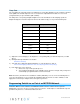
Scene Commands Supported as Controller Scene Commands Supported as Responder On Fast-on Off Fast-off Dim Brighten On Fast-on Off Fast-off Dim Brighten Software Configurable Yes RF Range 915 MHz X10 Support Yes X10 Addresses 1 optional (ships unassigned) INSTEON Device Category Dimmer switches INSTEON Device Subcategory Mechanical Mounting Wire Nuts Wires Mounts in single or multiple-ganged wall box. Control 200W less load for each immediately adjacent SwitchLinc Dimmer installed.
Certifications Safety tested for use in USA and Canada (ETL #3017581) Troubleshooting Problem Possible Cause Solution Make sure the circuit breaker is turned on The LED bar on SwitchLinc is not turning SwitchLinc is not getting on at all and SwitchLinc power won't control my light The switch I'm replacing only has two wires SwitchLinc is not receiving signals from INSTEON or X10 controllers Check wall box wires to ensure all connections are tight and no bare wires are exposed Check the light fixture
both INSTEON and X10 commands My light only turns off when I tap the paddle top on SwitchLinc, but I can brighten and dim it If the INSTEON device is still available, unlink it You may have removed an from SwitchLinc. See Removing SwitchLinc as INSTEON device that your an INSTEON Controller. SwitchLinc is trying to operate SwitchLinc is retrying the Perform a factory reset. See Factory Reset.
• • There might be loose connections within your home’s wiring GE 15 Amp Combination Arc Fault Breaker #THQL1115AFP2 Murray 2-Pole Combination Type Arc Fault Circuit Interrupter #MP215AFCP Install a powerline noise filter (such as a FilterLinc) between the output and the lead. The status LEDS are Dim the LEDs. See Changing the LED The status LEDS are too adjustable and might be set at Brightness.
Certification and Warranty Certification This product has been thoroughly tested by ITS ETL SEMKO, a nationally recognized independent third-party testing laboratory. The North American ETL Listed mark signifies that the device has been tested to and has met the requirements of a widely recognized consensus of U.S.