SwitchLinc™ Dimmer INSTEON® Dual-Band Remote Control Dimmer Owner’s Manual (rev 7.
The Basics ................................................................................................................................................... 3 Cautions and Warnings .............................................................................................................................. 3 Identifying the Electrical Wires in Your Home ........................................................................................... 3 Installation ...............................................
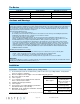
The Basics In the Box SwitchLinc Dimmer Quick Start Guide 2 screws and 4 wire nuts Tools Needed Slotted and Phillips screwdrivers Wire cutter/stripper Voltage meter Optional Accessories INSTEON app SmartLinc Hub Cautions and Warnings Read and understand these instructions before installing and retain them for future reference.
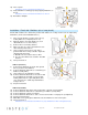
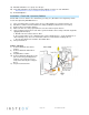
10) Turn on power SwitchLinc and its connected load will turn on 11) Verify SwitchLinc is working properly by tapping SwitchLinc on and off SwitchLinc and its connected load will turn on and off 12) Reinstall the wallplate Installation – Circuit with 2 Switches (a.k.a. 3-way circuit) Circuits with 2 switches are called 3-way circuits. Both switches in a 3-way circuit need to be replaced by SwitchLincs (and/or other INSTEON devices).
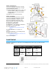
19) Add both SwitchLincs to a group. See “Groups” 20) Verify both SwitchLincs are working properly by tapping on and off on each SwitchLinc Both SwitchLincs and the connected load will remain in synch 21) Reinstall wallplates Installation – Circuit with 3 (or more) Switches Circuits with 3 or more switches are called 4-way (or 5-way, etc.) All switches in 3-way/4-way circuits need to be replaced by INSTEON devices.
In Box 2 (Traveler box) 12) Connect SwitchLinc bare wire to ground 1 13) Connect SwitchLinc white wire to neutral 14) Cap SwitchLinc red wire 15) Connect SwitchLinc black wire to same color traveler from Box 1 that you connected to line along with same color traveler wires leading to Box 3 16) Cap the last unused traveler wire(s) In Box 3 (Load box) 17) Connect SwitchLinc bare wire to ground 18) Connect SwitchLinc white wire to neutral 19) Connect SwitchLinc red wire to load 20) Connect SwitchLinc black wir
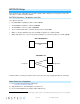
INSTEON Setup Some products have subtle differences in their setup procedures. Where necessary, please refer to the other device’s owner’s manual for details. INSTEON Controllers, Responders and Links Let’s define a few terms.
Controller LED will stop blinking 4) Test by tapping controller button on and off SwitchLinc will turn on (at desired brightness) and off Make SwitchLinc a Controller 1) 2) 3) 4) 5) Press and hold SwitchLinc Set button until it beeps LED will start blinking green Adjust responder to desired brightness/state Press and hold responder Set button until it double-beeps SwitchLinc will double-beep and its LED will stop blinking Test by tapping SwitchLinc paddle on and off Responder will turn on (at desired brig
6) Press and hold controller Set button until it double-beeps Controller LED will stop blinking 7) Test by tapping controller button on and off SwitchLinc and all scene responders will turn on (to desired brightness/states) and off Remove SwitchLinc as a Controller (Unlink) 1) Press and hold SwitchLinc Set button until it beeps LED will start blinking green 2) Press and hold SwitchLinc Set button until it beeps LED will start blinking red 3) Press and hold responder Set button until it double-beeps SwitchL
3) Push in Set button and hold it. Do not let go SwitchLinc will emit a long beep 4) When long beep stops, release Set button A few seconds will pass SwitchLinc will double-beep The connected load will turn on X10 Setup SwitchLinc ships with no X10 address assigned. Add X10 Address 1) Turn SwitchLinc on. 2) Press and hold Set button until it beeps.
1) Turn SwitchLinc off 2) Tap Set button SwitchLinc will beep 3) Test: a. Brighten SwitchLinc to a random brightness level (e.g. 75%) b. Turn SwitchLinc off c. Turn SwitchLinc back on Light will turn on at the defined brightness level Local Ramp Rate Default = ½ second. The local ramp rate is the time it takes for SwitchLinc to reach 100% brightness (from off) when controlled at the paddle. It is adjustable from instant to 8 minutes (with software) and instant to 5 seconds (using Set button).
Error Blink Default = on. This setting is adjustable via software or a central controller only. SwitchLinc LED blinks for a few seconds if one or more responders do not acknowledge a message.
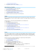
X10 X10 address 1 optional (comes unassigned) X10 transmitter Yes X10 receiver Yes X10 status response Supported X10 resume dim Supported (by setting local on-level to zero) X10 minimum transmit level 3.
Troubleshooting Problem SwitchLinc’s LEDs and connected load will not turn on Possible Cause SwitchLinc is not getting power The switch I'm replacing only has two wires SwitchLinc needs a neutral wire in order to operate SwitchLinc is able to communicate with another INSTEON device SwitchLinc and the other device are out of range The light turned on by itself The other device is near a localized powerline noise source or attenuator Another controller, a timer or a stray X10 signal was received It ta
LED Brightness If you have tried these solutions, reviewed this Owner's Manual, and still cannot resolve an issue you are having with SwitchLinc Dimmer, please call the INSTEON Support Line at 1-800-762-7845 Page 15 of 16 Rev: 3/29/2013 10:32 AM
Certification and Warranty Certification This product has been thoroughly tested by Intertek ETL, a nationally recognized independent third-party testing laboratory. The North American ETL Listed mark signifies that the device has been tested to and has met the requirements of a widely recognized consensus of U.S.