
Datasheet
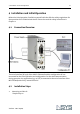

12 4. Installation and Initial Operation
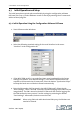
2. Inserting the SIM card
Attention! When the automatic module initialization sequence (see Chap. 4) is used
to automatically transfer the PIN of the SIM card, this function must be deactivated
for a while for a new SIM card with another PIN. This may otherwise lead to the
blocking of the SIM card (after three incorrect inputs).
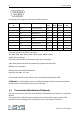
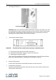
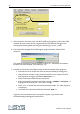
3. Connection of Power Supply:
Attention! The value for Pin 1 stated on the cover top is a maximum value.
a) Connection of the ground wire GND at terminal 2.
b) Connection of the power supply 12..24 V DC at terminal 1.
c) Switching on the power supply
After successful installation, the power LED will be green. The LED GSM net flashes
green after approximately 5 s according to a clock pulse of 600 ms.
4. Connect GSM antenna
Connect the GSM antenna to the FME connector on the front panel.
5. Connection PC/Terminal
Plug the enclosed RS232 interface cable into the cover front, attach it with screws
and connect it with the PC.
Version 1.00 / 09.04