Digital Light Processing Projector DLV-100 Instruction Manual
IMPORTANT INFORMATION Precautions Please read this manual carefully before using your Integra Projector DLV-100 and keep the manual handy for future reference. Your serial number is located on the bottom of your DLV-100. Record it here: CAUTION To turn off main power, be sure to remove the plug from power outlet. The power outlet socket should be installed as near to the equipment as possible, and should be easily accessible. CAUTION TO PREVENT SHOCK, DO NOT OPEN THE CABINET.
Important Safeguards CAUTION These safety instructions are to ensure the long life of your projector and to prevent fire and shock. Please read them carefully and heed all warnings. Do not unplug the power cable from the wall outlet under any one of the following circumstances. Doing so can cause damage to the projector: Installation * While the Hour Glass icon appears. * While the message "Please wait a moment." appears. This message will be displayed after the projector is turned off.
Cleaning 1. Unplug the projector before cleaning. 2. Clean the cabinet periodically with a damp cloth. If heavily soiled, use a mild detergent. Never use strong detergents or solvents such as alcohol or thinner. 3. Use a blower or lens paper to clean the lens, and be careful not to scratch or mar the lens. Lamp Replacement • To replace the lamp, follow all instructions provided on page 44. • Be sure to replace the lamp when the message "The lamp has reached the end of its usable life.
TABLE OF CONTENTS 1. INTRODUCTION Introduction to the Projector DLV-100 ............................. 6 Getting Started ............................................................... 6 What’s in the Box ............................................................ 7 Getting to Know Your Projector DLV-100 ........................ 8 Front / Side Features ................................................. 8 Attaching the lens cap ................................................ 8 Rear / Side Features ..........
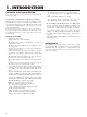
1. INTRODUCTION Introduction to the Projector DLV-100 This section introduces you to your new Projector and describes the features and controls. Congratulations on Your Purchase of The Projector DLV-100 The DLV-100 is one of the very best projectors available today. The DLV-100 enables you to project precise images up to 200 inches across (measured diagonally) from your PC or Macintosh computer (desktop or notebook), VCR, DVD player, document camera, a laser disc player or PC Card Viewer.
What's in the Box? Make sure your box contains everything listed. If any pieces are missing, contact your dealer. Please save the original box and packing materials if you ever need to ship your Projector DLV-100.
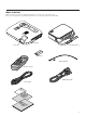
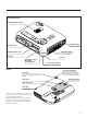
Getting to Know Your Projector DLV-100 Front/ Side Features Controls ENTER SE LE CT U PC CA A RD AD UTO JU AC ST CE SS NCEL N CA ME SO UR CE O ST N / AN DB Y ST AT PO US WE R Ventilation (inlet) Adjustable Tilt Foot Adjustable Tilt Foot Button Zoom Ring Focus Ring Remote Sensor Lens Lens Cap Attaching the lens cap to the lens hood with the supplied string and rivet 8 ○ ○ ○ ○ ○ ○ ○ ○ ○ ○ ○ ○ ○ ○ ○ ○ ○ ○ ○ ○ ○ ○ ○ ○ ○ ○ ○ ○ ○ ○ ○ ○ ○ ○ ○ ○ ○ ○ ○ ○ ○ ○ ○ ○ ○ ○ ○ ○ 1.
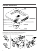
Rear/ Side Features Monaural Speaker (1W) S TU R TA S WE O P / D N N O TA S Y B E C R U O S C P AU DIO ME N T TO S U U A DJ A S S E C C A D R A C U T C LE E S ENTER RG B S-V IDE O PC CO NT RO L CA NCEL VID EO Remote Sensor Ventilation (inlet) US B PC CA RD AC IN Ventilation (outlet) Terminals and PC card Heated air is exhausted from here AC Input Rear Foot Slot for Kensington MicroSaver Security System Bottom Spacer (black rubber) Spacer (black rubber) Rear Foot Rotate to fine-adjus
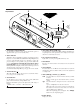
2 Top Features R E W O P S TU TA S / D N N O TA S 4 Y B E C R U O S 3 10 5 1 9 AU C P DIO U N E C C A T TO S U U A DJ A S S D R A C ME S RG O T C IDE CO LE S-V PC E ENTER B CA NT RO L NCEL 6 VID EO 7 US B PC CA 8 RD 1. Power Button (ON / STAND BY) Use this button to turn the power on and off when the power is supplied and the projector is in standby mode. 2.
Terminal Panel Features S TU R E W O P 1 / D N N O TA S 2 Y B E C R U O S 3 4 AU C P DIO U N E C C A T TO S U U A DJ A S S D R A C ME CO NT T C O LE IDE E S-V ENTER 5 B PC S RG CA 6 RO L VID NCEL EO US B PC CA RD 7 8 1. Audio Input Mini Jack (3.5 mm ∅) This is where you connect audio output from your computer, VCR, DVD player or laser disc player. A commercially available audio cable is required. 2.
Remote Control Features Supplied Remote Control 1 1. Infrared Transmitter Direct the remote control toward the remote sensor on the projector cabinet. 2. Standby/On Button If the main power is applied, you can use this button to turn your projector on or put it in standby. 3. S-Video Button Press this button to select an S-Video source from a VCR. 4. Video Button Press this button to select an NTSC, PAL, SECAM or NTSC4.
Operating Range Remote Control Battery Installation The infrared signal operates by line-of-sight up to a distance of approximately 22 feet (7m) and within a 60-degree angle of the remote sensor. The projector will not function if there are objects between the remote control and the remote sensor on the projector or if strong light falls on the remote sensor. A weak battery will also prevent the projector from operating 1 Remove the battery compartment cover by pressing the tab and lifting up the cover.
2. INSTALLATION This section describes how to set up your projector DLV-100 and how to connect video and audio sources. Setting up Your Projector Your Projector DLV-100 is simple to set up and use. But before you get started, you must first: 1. Determine the image size. 2. Set up a screen or select a non-glossy white wall onto which you can project your image. Ensure that the power cable and any other cables connecting to video sources are disconnected before moving the projector.
Distance Chart C Lens Center D Throw Distance Screen Top α B Lens Offset from Center of Projector Screen Center 2.97” (75.5mm) C Throw Distance Screen Center B Lens Center D Screen Bottom 1.5”(38mm) α Projector feet B=Vertical distance between lens center and screen center D=Vertical distance between lens center and top of screen (bottom of screen for desktop) C=Throw distance α=Throw angle NOTE: Distances may vary +/-5%.
Wiring Diagram To video, S-video, and audio inputs on the projector. VCR, DVD Player or LaserDisc Player AUDIO Document Camera RGB RGB Signal cable (supplied) To mini D-Sub 15-pin connector on the projector. It is recommended that you use a commercially available distribution amplifier if connecting a signal cable longer than the supplied cable.
Connecting Your PC IBM VGA or Compatibles (Notebook type) RGB signal cable (supplied) To mini D-Sub 15-pin connector on the projector. It is recommended that you use a commercially available distribution amplifier if connecting a signal cable longer than the supplied one.
Connecting Your Macintosh Computer Macintosh (Notebook type) S TA P TU S O W E R / D N N O TA S B Y S O U R C E P AU DIO C U EN T ER CO NT RO L T C LE E S PC N T TO S U U A DJ A S S E C C A D R A S-VI DE O RGB Signal cable (supplied) ME C RG B CAN CEL VIDE O US B PC CA RD AC IN AU DIO RG BI AU NP DIO RG B S-V PC Audio cable (not supplied) UT CO IDE NT O RO L VID EO Macintosh (Desktop type) NOTE: The new Macintosh computer such as G3 will have the 15 pin HD conne
Connecting Your DVD Player S TU R TA S WE O P DVD player / D N N O TA S Y B E C R U O S C P AU DIO ME U T EN T ER CO NT RO L C LE E S S-VI DE O PC N T TO S U U A DJ A S S E C C A D R A C RG B CAN CEL VIDE O US B PC CA RD AC IN Cr Cb RG BI Y Cr L R NP AU DIO Cb UT RG B S-V IDE Y O PC White CO NT RO L VID EO Red 15-pin-to-RCA 3 cable (not supplied) (Component V ) Audio Equipment Audio cable (not supplied) L R White Red You can connect your projector to a D
Connecting Your VCR or Laser Disc Player VCR/ Laser disc player S TA P TU S O W E R / D N N O TA S B Y S O U R C E AU P DIO C ME DE NT O RO U CO EN T ER S-VI PC T C LE E S B N T TO S U U A DJ A S S E C C A D R A C RG CAN L VIDE CEL O US B PC CA RD AC IN S-V IDE O AU DIO L R S-video cable (not supplied) VID EO RG B S-V IDE O White PC CO NT RO L VID EO Red Audio equipment Document camera Audio cable (not supplied) VID L EO R White Red Video cabl
About Startup screen (Menu Language Select screen) When you first turn on the projector, you will get the Startup screen. This screen gives you the opportunity to select one of the seven menu languages: English, German, French, Itilan, Spanish,Swedish and Japanese. To select a menu language, follow these steps: 1. Use the Select ▲ or ▼ button to select one of the seven languages for the menu. 2. Press the Enter button to execute the selection. 3.
3.OPERATION Connecting the Power Cable and Turn on the Projector Before you turn on your projector, ensure that the computer or video source is turned on and that your lens cap is removed. NOTE: Do not disconnect the power cable during this time. Then, unplug the power cable. The power indicator will go out. Status of indicator light: turn on Normal mode: 1 stand by Connect the supplied power cable to the projector.
Press the RGB, VIDEO or S VIDEO button on the remote control, or the Source button on the projector cabinet to select “Video” (VCR, document camera, or laser disc player), S-Video”, “RGB” (computer or DVD with component output) or “PC Card Viewer” (slides on a CompactFlash card) to display the image. Or press the “Menu” button on the remote control or the cabinet and use the menu to select your video source: “Video”, “S-Video”, “RGB” or “PC Card Viewer”.
Adjust the Tilt Foot 1) Lift the front edge of the projector. 2) Press the Tilt button on the top of the projector to extend the adjustable tilt foot (maximum height). [Poor picture] EN T ER CAN PC SO ON TU /STA ND WE CT LE U A AD UTO JU ST ME CE BY S PO CEL SE SS N R CE 2 STA UR CA DA C 1 Adjust the Image Using Auto Adjust The Auto Adjust function automatically optimizes the image in RGB mode. R 1 [Normal picture] 3) Press and hold the Tilt button.
Basic Operation Volume control Selecting the computer or video source Sound level from the speaker on the projector can be adjusted. NOTE: When the menu or the magnifying glass appears, you cannot adjust the volume. increase volume Volume bar If the projector cabined is used, each time the Source button is pressed, the input source will change as follows: → RGB → Video → S-Video → PC Card Viewer decrease volume If no input signal is present, the input will be skipped.
Using Magnify button 4. Return the image to the original size. You can use Magnify button to draw your audience's attention to the portion of a projected image you want. Press the Magnify button. Freezing a picture Press the Freeze button to freeze a picture. Press again to resume motion. Use the Select button to move the magnifying glass. Enlarging and Moving a Picture You can enlarge the area you want up to 400 percent. To do so: 1. Press the Magnify button. 2.
Using the Menus NOTE: The on-screen menu may not be displayed correctly while interlaced motion video image is projected. 2. Use the ▲ or ▼ button to highlight your selection and press the Enter button to place a check mark next to an option. This action enables that feature. Press the Enter button again to clear the check box. 1. Press the "Menu" button on the remote control or projector cabinet to display the Advanced Menu or Basic/Custom Menu.
Using a USB Mouse Using a USB mouse gives you a smooth operation. A commercially available USB mouse is required. NOTE:There may be some brands of USB mouse that the projector does not support. Operate the Menus using the USB mouse Mouse Cursor When connecting a USB mouse to the projector, you get a mouse cursor on the screen. Unless you use your USB mouse within 10 seconds, the mouse cursor disappears. Menu Display Clicking with a mouse button displays the menu. Clicking displays the pull-down menu.
Menu Tree Advanced Menu Source Select Picture Volume Image Options Color Management Projector Options Tools Information RGB Video S-Video PC Card Viewer Brightness/Contrast/Color/Hue/Sharpness Volume Keystone Lamp Mode Advanced Options Factory Default High-Bright/Normal Aspect Ratio Noise Reduction Position/Clock Resolution Video Filter Normal/Zoom/Wide Zoom/Cinema Off/Low/Medium/High Horizontal/Vertical/Clock/Phase Auto/Native On / Off All Data/Current Signal Gamma Correction Color Matrix White Balan
Menu Elements Tab Title bar Close Button Highlight Radio Button OK Button Cancel Button Solid triangle Check box Grip icon Tool bar Slide bar ○ ○ ○ ○ ○ ○ ○ ○ ○ ○ ○ ○ ○ ○ ○ ○ ○ ○ ○ ○ ○ ○ ○ ○ ○ ○ ○ ○ ○ ○ ○ ○ ○ ○ ○ ○ ○ ○ ○ ○ ○ ○ ○ ○ ○ ○ ○ ○ ○ ○ ○ ○ ○ ○ ○ ○ ○ ○ ○ ○ ○ ○ ○ ○ Menu windows or dialog boxes typically have the following elements: Title bar: Indicates the menu title. Highlight: Indicates the selected menu or item. Solid triangle: Indicates further choices are available.
Menu Descriptions & Functions Source Select Enables you to select a video source such as a VCR, DVD player, laser disc player, computer or document camera depending on what is connected to your inputs. Press the "Select" button on the projector cabinet or ▲▼ buttons on your remote control to highlight the menu for the item you want to adjust. The launcher is a tool bar including the following buttons: Drag ........... Drags to move the tool bar. (for USB mouse operation only) Prev ............
Image Options Aspect Ratio (not available for RGB and PC Card Viewer) Aspect Ratio allows you to select the best Aspect mode to display your source image. When 4:3 is selected from the source (i.e.
Noise Reduction (not available for RGB and PC Card Viewer) You can select three levels video noise reduction. NOTE: The lower the Noise Reduction level, the better the image quality by way of higher video bandwidth. Position/ Clock (when Auto Adjust is off) Resolution (when Auto Adjust is off) This allows you to activate or deactivate the Advanced AccuBlend feature. Auto ............ Turns on the Advanced AccuBlend feature.
Color Management Projector Options Gamma Correction (not available for PC Card Viewer) Use the or button to choose "Normal" when in a lighted room and "Natural 1&2" when in a darkened room. "Natural 1" for better flesh tone; "Natural 2" for true reproduction of middle tones. Each mode is recommended for : Normal ....... For the regular picture Natural 1 ..... For true color reproduction of natural tones Natural 2 .....
Projector Pointer: This option is not available on this model. Menu Display Time : This option allows you to select how long the projector waits after the last touch of a button to turn off the menu. The preset choices are "Manual", "Auto 5 sec", "Auto 15 sec", and "Auto 45 sec". The "Auto 45 sec" is the factory preset. Manual ....... The menu can be turned off manually. Auto 5 sec .. The menu will automatically be turned off in 5 seconds if no buttons are pressed within 5 seconds. Auto 15 sec ...
Mouse Settings: This option lets you to change your USB mouse settings. The mouse settings feature is available for USB mouse only. Choose the settings you want: Mouse Button ........... "Right Hand" or "Left Hand" Mouse Sensitivity .....
Auto Start: Turns the projector on automatically when the power cable is inserted into an active power outlet. This eliminates the need to always use the "Power" button on the projector cabinet or remote control. [Page 5] Power Management: When this option is on and there is no RGB input for five minutes or more, the projector will automatically turn itself off. Power Off Confirmation: This option determines whether a confirmation dialog for turning off the projector will appear or not.
PC Card Files: Displays a list of all the files stored in the CompactFlash card so that you can select a file you want to display. You can also sort files by file name or date, or display the file. Although a list of all the files in the CompactFlash card is displayed, you can view files in idx, text, HTML, JPEG and BMP format only. Selecting BMP and JPEG files automatically switches to the PC Card Viewer source.
2. Use the button and then ▼ button to select “Logo”. 3. Press the Enter on the remote control or the cabinet. You will get the confirmation dialog box. Information 4. Select “OK” and press the Enter button. This completes changing a logo for the background. * Once you have changed the background from the Integra logo to another, you cannot return the logo to background even by using Factory Default. To do so, repeat the above steps.
Using the PC Card Viewer function Features The Viewer feature allows slides stored on a CompactFlash memory card (referred to as CompactFlash card in this manual) to be displayed on the projector. Even if no computer is available, presentations can be conducted simply with the projector. This feature is convenient for holding presentations at meetings and in offices, as well as for playing images taken on digital cameras.
Operating the PC Card Viewer Function from the Projector (playback) This section describes the operation for showing slides of presentation documents created using the PC Card Viewer function with the projector. It is also possible to make slides directly from the images projected with the projector. Drag: Drags to move the tool bar. This is available for USB mouse operation only. Prev: Returns to the previous slide or folder. Or this lets you play slides back in reverse.
Capturing Images Displayed on the Projector Deleting Captured Images Prev Storing images displayed on the projector on the CompactFlash card Play Jump Setup View Drag Preparations: Insert the CompactFlash card into the card slot. Insert the CompactFlash card with the side with the insertion direction arrow on the top. * Press the eject button to eject the card. 1. Project the image you wish to store on the projector. 2. Select the “Capture” from the Tools menu.
Terminology PC card This is the name of a card currently being standardized by the Japan Electronic Industry Association (JEIDA) and PCMCIA (Personal Computer Memory Card Interface Association) of the United States. ATA card A type of PC card. ATA was originally a type of interface between computers and fixed disk devices. The ATA card is a standard card-type recording medium. CompactFlash CompactFlash card is a small removable card conforming to ATA specifications.
4. MAINTENANCE This section describes the simple maintenance procedures you should follow to replace the lamp. 3 Remove the lamp housing by pulling out the handle. NOTE: There is an interlock on this case to prevent the risk of electrical shock. Do not attempt to circumvent this interlock. Replacing the Lamp After your lamp has been operating for 1500 hours (1000 hours in High-Bright mode) or longer, the “Status” light in the cabinet will go on and the message will appear.
5. TROUBLESHOOTING This section helps you resolve problems you may encounter while setting up or using the projector. Power/Status Light Messages Condition Power Indicator Status Indicator Note Standby Steady orange – – Cooling down Blinking green – Blinks green for 90 seconds Lamp in Normal mode Steady green – – Lamp in High-Bright mode Steady green Steady green – Retrying to turn on lamp Steady green Blinking orange The projector retries 3 times at an interval of 15 sec for max.
Common Problems & Solutions Problem Check These Items Does not turn on • Check that the power cable is plugged in and that the power button on the projector cabinet or the remote control is on. • Ensure that the lamp cover is installed correctly. See page 44. • Check to see if the projector has overheated or the lamp usage exceeds 1100 hours (up to 1600 hours : Normal mode).
6. SPECIFICATIONS This section provides technical information about the DLV-100 Projector's performance Model Number DLV-100 Optical DMD™ Single Chip Digital Micromirror Device(DMD™), 1024x768 dots Lens Manual zoom, Manual focus: F2.6 – 2.8 f= 28.3 – 34.0mm Lamp 135 W NSH lamp (The lamp is warranted for 1000 hours of operation time within 6 months.) Image Size 30 - 200 inches (0.8 - 5.1 m) diagonal Projection Distance 3.8 – 31.7ft (1.16 – 9.
Cabinet Dimensions PC CONTROL AUDIO RGB S-VIDEO USB AC IN ~ VIDEO PC CARD PC CARD ACCESS STATUS ON/ STAND BY AUTO ADJUST SOURCE NT CA ER E POWER NC EL SELECT MENU 196 (7.7”) 238 (9.4”) 243 (9.6”) 43.5 (1.71”) Lens center Lens center 53 (2.1”) 29.5 (1.16”) 8 (0.
D-Sub Pin Assignments Mini D-Sub 15 Pin Connector 5 4 3 2 1 10 9 8 7 6 15 14 13 12 11 Pin No. Signal Level Video signal : 0.
Compatible Input Signal List Signal # # # # # # # # # # # # # # # # # # # # NTSC PAL SECAM VESA IBM MAC MAC MAC VESA VESA IBM VESA IBM VESA IBM IBM VESA VESA VESA VESA VESA MAC VESA VESA VESA MAC VESA VESA VESA MAC SUN SGI VESA VESA MAC HP SUN VESA VESA HDTV (1080i)(1125i) HDTV (1080i)(1125i) HDTV (720p)(750p) SDTV (480p)(525p) SDTV (480i)(525i) VESA VESA VESA VESA Resolution ( Dots ) 640 640 640 640 640 640 640 640 640 720 720 720 720 800 800 800 800 800 832 1024 1024 1024 1024 1024 1024 1152 1152 1152
PC Control Codes Cable Connection Function Code Data Communication Protocol Baud rate: 38400 bps POWER ON 02H 00H 00H 00H 00H 02H Data length: 8 bits POWER OFF 02H 01H 00H 00H 00H 03H Parity: No parity INPUT SELECT RGB 02H 03H 00H 00H 02H 01H 01H 09H Stop bit: One bit INPUT SELECT VIDEO 02H 03H 00H 00H 02H 01H 06H 0EH X on/off: None Full duplex INPUT SELECT S-VIDEO 02H 03H 00H 00H 02H 01H 0BH 13H INPUT SELECT PC CARD VIEWER 02H 03H 00H 00H 02H 01H 1FH 27H PICTURE MUTE ON 02H 10H 00
Integra Division of ONKYO U.S.A. CORPORATION 18 Park Way, Upper Saddle River, N.J. 07458, U.S.A. Tel: 201-785-2600 Fax: 201-785-2650 http://www.integrahometheater.com Integra Division of ONKYO CORPORATION Sales & Product Planning Div.