AV Receiver DTR-40.
Safety Information and Introduction WARNING: TO REDUCE THE RISK OF FIRE OR ELECTRIC SHOCK, DO NOT EXPOSE THIS APPARATUS TO RAIN OR MOISTURE. CAUTION: TO REDUCE THE RISK OF ELECTRIC SHOCK, DO NOT REMOVE COVER (OR BACK). NO USER-SERVICEABLE PARTS INSIDE. REFER SERVICING TO QUALIFIED SERVICE PERSONNEL.
Safety Information and Introduction Precautions 1. Recording Copyright—Unless it’s for personal use only, recording copyrighted material is illegal without the permission of the copyright holder. 2. AC Fuse—The AC fuse inside the unit is not userserviceable. If you cannot turn on the unit, contact your Onkyo dealer. 3. Care—Occasionally you should dust the unit all over with a soft cloth. For stubborn stains, use a soft cloth dampened with a weak solution of mild detergent and water.
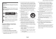
Safety Information and Introduction Supplied Accessories Make sure you have the following accessories: Indoor FM antenna (➔ page 18) ■ Aiming the remote controller To use the remote controller, point it at the AV receiver’s remote control sensor, as shown below.
Safety Information and Introduction Table of Contents Safety Information and Introduction Important Safety Instructions ......................................2 Precautions ...................................................................3 Supplied Accessories...................................................4 Table of Contents..........................................................5 Features .........................................................................6 Front & Rear Panels.................
Safety Information and Introduction Features Amplifier • 110 Watts/Channel @ 8 ohms (FTC) • 170 Watts/Channel @ 6 ohms (IEC) • 185 Watts/Channel @ 6 ohms (JEITA) • WRAT–Wide Range Amplifier Technology (5 Hz to 100 kHz bandwidth) • Linear Optimum Gain Volume Circuitry • H.C.P.S.
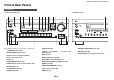
Safety Information and Introduction Front & Rear Panels Front Panel (North American models) For detailed information, see the pages in parentheses.
Safety Information and Introduction Display s For detailed information, see the pages in parentheses. Speaker/channel indicators Z3 (Zone 3) indicator (71) Input indicators (92) HDMI indicator (66) DIGITAL indicator ANALOG indicator Listening mode and format indicators (37) Bi AMP indicator M.
Safety Information and Introduction Rear Panel REMOTE CONTROL jack ZONE 2 OUT V jack USB port ZONE 2 and ZONE 3 PRE/LINE OUT jacks ETHERNET port FM ANTENNA jack and AM ANTENNA terminal RS232 port Terminal for control.
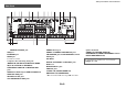
Safety Information and Introduction Remote Controller Controlling the AV Receiver To control the AV receiver, press Receiver to select Receiver mode. You can also use the remote controller to control Integra/Onkyo Blu-ray Disc/DVD player, CD player, and other components. See “Entering Remote Control Codes” for more details (➔ page 77). For detailed information, see the pages in parentheses.
Connections Connecting the AV Receiver Front high right Front wide right Front right Front left Front wide left Front high left Center Connecting Your Speakers Speaker Configuration The following table indicates the channels you should use depending on the number of speakers that you have. No matter how many speakers you use, a powered subwoofer is recommended for a really powerful and solid bass.
Connections Attaching the Speaker Cable Labels The speaker terminals are color-coded for identification purpose. Speaker Color Front left, Front high left, Front wide left, Zone 2 left, Zone 3 left White Front right, Front high right, Front wide right, Zone 2 right, Zone 3 right Red Center Green Surround left Blue Surround right Gray Surround back left Brown Surround back right Tan terminals, and negative (–) terminals only to negative (–) terminals.
Connections Using Powered Subwoofers Bi-amping the Front Speakers Connecting a Power Amplifier Important: LINE INPUT LINE INPUT • When making the bi-amping connections, be sure to remove the jumper bars that link the speakers’ tweeter (high) and woofer (low) terminals. • Bi-amping can be used only with speakers that support biamping. Refer to your speaker manual. LINE INPUT LINE INPUT Bi-amping provides improved bass and treble performance.
Connections About AV Connections Connecting AV components a HDMI cable : Video & Audio TV, projector, etc. *1 • Push plugs in all the way to make good connections (loose connections can cause noise or malfunctions). • To prevent interference, keep audio and video cables away from power cords and speaker cables. Right! ■ Optical digital audio Optical digital connections allow you to enjoy digital sound such as PCM*2, Dolby Digital or DTS. The audio quality is the same as coaxial.
Connections Connecting Components with HDMI Satellite/cable set-top box, etc. Personal computer TV, projector, etc. Camcorder, etc. Blu-ray Disc/DVD player Game console Set top box/digital video recorder, etc. * * If your TV doesn’t support Audio Return Channel (ARC), you need to connect an optical digital cable together with the HDMI cable to the AV receiver.
Connections Connecting Your Components The on-screen menus appear only on a TV that is connected to HDMI OUT MAIN. If your TV is connected to other video outputs, use the AV receiver’s display when changing settings. Connect your components to the appropriate jacks. The default input assignments are shown below. See “Connection Tips and Video Signal Path” for more information (➔ page 91). ✔: Assignment can be changed (➔ pages 53, 54). No.
Connections No. Jack/Port output from the HDMI outputs. However, if you have assigned the HDMI inputs to the PC input selector, the AV receiver will output signals received from the HDMI inputs instead of signals from PC IN. To have the signals output from PC IN, select “- - - - -” for “PC” in the “HDMI Input” setting (➔ page 52). Components VIDEO IN IN 1 (BD/DVD) Blu-ray Disc/DVD player ✔ IN 2 (CBL/SAT) Satellite/cable set-top box, etc.
Connections Connecting the Antennas Connecting the Power Cord This section explains how to connect the supplied indoor FM antenna and AM loop antenna. The AV receiver won’t pick up any radio signals without any antenna connected, so you must connect the antenna to use the tuner. North American models 1 Connect the supplied power cord to the AV receiver’s AC INLET. Australian models To AC wall outlet Push. Insert wire. Release. Insert the plug fully into the jack.
Turning On & Basic Operations Turning On/Off the AV Receiver Turning On 1 On/Standby Press or On/Standby on the front panel. Press Receiver followed by Receiver on the remote controller. The AV receiver comes on and its display lights. Turning Off 1 Press or On/Standby on the front panel. Press Receiver followed by Receiver on the remote controller. The AV receiver will enter standby mode.
Turning On & Basic Operations Initial Setup This section explains the settings that we recommend you to make before using the AV receiver for the very first time. A setup wizard is launched upon first-time use to let you perform those settings. Selecting the Language for the Onscreen Setup Menus This step determines the language used for the onscreen setup menus. See “Language” in “OSD Setup” (➔ page 65). Tip The on-screen menus appear only on a TV that is connected to HDMI OUT MAIN.
Turning On & Basic Operations Source Connection This step checks the connection of source components. 1 2 3 4 Use / to select one of the following options, and then press Enter. `Yes, Continue: Performs the checkings. `No, Skip: Skips this step and continues to “Remote Mode Setup”. Select the input selector for which you want to check the connection and press Enter. The picture of the corresponding source should appear on screen with a verification prompt.
Turning On & Basic Operations Playback The on-screen information appears only on a TV that is connected to HDMI outputs. If your TV is connected to other video outputs, use the AV receiver’s display when changing settings. 1 Press Receiver followed by an Input Selector button. 2 Start playback on the source component.
Turning On & Basic Operations Controlling Contents of USB or Network Devices Press USB or NET first. Top Menu This button displays the top menu for each media or service. This button stops playback. / and Enter Mode These buttons navigate through the menus. You can switch between Standard Mode and Extended Mode. / This button cycles through pages. Random This button performs random playback. Playlist / In Standard Mode (iPod/iPhone), this button selects playlists. This button starts playback.
Turning On & Basic Operations Understanding Icons on the Display This section describes icons that appear on the AV receiver’s display during media playback. Icon Playing an iPod/iPhone via USB 3 Press Mode repeatedly to switch to Extended Mode (Music) or Extended Mode (Video). The on-screen information appears only on a TV that is connected to HDMI outputs. A list of your iPod/iPhone model’s contents appears. Pause This section explains how to play music/video files on the iPod/iPhone.
Turning On & Basic Operations Extended Mode (Music) Control The music content information is displayed (lists are displayed), and you can control the music content while looking at the screen. Top screen list: Playlists, Artists, Albums, Genres, Songs, Composers, Shuffle Songs, Now Playing. Note Playing a USB Device The on-screen information appears only on a TV that is connected to HDMI outputs. This section explains how to play music files from a USB device (e.g., USB flash drives and MP3 players).
Turning On & Basic Operations Listening to vTuner Internet Radio You need to connect the AV receiver to your home network (➔ page 97). The on-screen information appears only on a TV that is connected to HDMI outputs. The vTuner Internet Radio Service is a portal site featuring radio stations from all over the world. You can search for stations by categories such as genre or location. The AV receiver is preinstalled with this service. 1 Press NET.
Turning On & Basic Operations Registering Other Internet Radio You need to connect the AV receiver to your home network (➔ page 97). The on-screen information appears only on a TV that is connected to HDMI outputs. Internet radio URLs in the following formats are supported: PLS, M3U, and podcast (RSS). However, depending on the type of data or audio format used by the Internet radio station, you may not be able to listen to some stations.
Turning On & Basic Operations Playing Music Files on a Server 5 Use / to select an item, and then press Enter or to start playback. 5 You need to connect the AV receiver to your home network (➔ page 97). The on-screen information appears only on a TV that is connected to HDMI outputs. Tip My favorite song 1 0 : 11 Artist name My favorite album This section explains how to play music files on a computer or media server through the AV receiver (Server Playback).
Turning On & Basic Operations 3 Move your cursor and click on “Turn on media streaming”. A list of media server appears. Wording may vary slightly depending on the network location. 4 On the “Media streaming options”, select the AV receiver and confirm that it is set to “Allow”. 5 Click “OK” to close the dialog box. This completes the Windows Media Player 12 configuration. You can now play the music files in your Windows Media Player 12 library.
Turning On & Basic Operations ■ Creating a shared folder Playing music files on a shared folder 1 2 3 4 Right-click the folder that you want to share. In order to enjoy Home Media, you must first create a shared folder on your computer. 5 Under “Network File and Folder Sharing”, select “Share”. 6 Select “Properties”. On the “Sharing” tab, select “Advanced Sharing”. 1 Check the check box of “Share this folder” and then click “OK”.
Turning On & Basic Operations ■ Auto tuning mode ■ Tuning into stations by frequency You can tune into AM and FM stations directly by entering the appropriate frequency. 1 Press Tuning Mode so that the AUTO indicator lights on the AV receiver’s display. 1 2 Press Tuning / . Searching stops when a station is found. Tuning into Radio Stations When tuned into a station, the TUNED indicator lights. When tuned into a stereo FM station, the FM STEREO indicator lights as shown.
Turning On & Basic Operations Using RDS (excluding North American models) RDS works only in areas where RDS broadcasts are available. When tuned into an RDS station, the RDS indicator lights. When the station is broadcasting text information, the text can be displayed. ■ What is RDS? RDS stands for Radio Data System and is a method of transmitting data in FM radio signals. It was developed by the European Broadcasting Union (EBU) and is available in most European countries.
Turning On & Basic Operations RDS program types (PTY) Type Display None None News reports News Current affairs Affairs Information Info Sport Sport Education Educate Drama Drama Culture Culture Science and technology Science Varied Varied Pop music Pop M Rock music Rock M Middle of the road music Easy M Light classics Light M Serious classics Classics Other music Other M Weather Weather Finance Finance Children’s programmes Children Social affairs Social Religion R
Turning On & Basic Operations Using Basic Functions Using the Automatic Speaker Setup With the supplied calibrated microphone, Audyssey 2EQ® automatically determines the number of speakers connected, their size for purposes of bass management, optimum crossover frequencies to the subwoofer (if present), and distances from the primary listening position.
Turning On & Basic Operations 1 2 Turn on the AV receiver and the connected TV. On the TV, select the input to which the AV receiver is connected. 5 Set the speaker setup microphone at the Main Listening Position , and connect it to the Setup Mic jack. Setup Mic jack Speaker setup microphone 6 The speaker setting menu appears. Note • The on-screen menus appear only on a TV that is connected to HDMI OUT MAIN.
Turning On & Basic Operations Error Messages Changing the Speaker Setup Manually While Audyssey 2EQ® Room Correction and Speaker Setup is in progress, one of the error messages below may appear. You can manually make changes to the settings found during Audyssey 2EQ Room Correction and Speaker Setup. See also: • “Speaker Configuration” (➔ page 55) • “Speaker Distance” (➔ page 56) • “Level Calibration” (➔ page 56) • “Equalizer Settings” (➔ page 56) 2EQ: Auto Setup AUDYSSEY Ambient noise is too high.
Turning On & Basic Operations Using the Listening Modes Selecting Listening Modes See “About Listening Modes” for detailed information about the listening modes. ■ Listening Mode Buttons Press Receiver first. Movie/TV button This button selects the listening modes intended for use with movies and TV. Music button This button selects the listening modes intended for use with music. Game button This button selects the listening modes intended for use with video games.
Turning On & Basic Operations Guide (Speaker layout) button Speaker Layout The illustration shows which speakers are activated in each channel. See “Speaker Configuration” for the speaker setup (➔ page 55). *1 Listening mode buttons Input Source The following audio formats are supported by the listening modes. This is mono (monophonic) sound. This is stereo (stereophonic) sound. Two independent audio signal channels are reproduced through two speakers. *1 This is 5.1-channel surround sound.
Turning On & Basic Operations ■ Onkyo-Original DSP Listening Modes Listening Mode Description Orchestra Suitable for classical or operatic music, this mode emphasizes the surround channels in order to widen the stereo image, and simulates the natural reverberation of a large hall.
Turning On & Basic Operations ■ Listening Modes Listening Mode Description Direct In this mode, audio from the input source is output without surround-sound processing. The speaker configuration (presence of speakers) and speaker distance settings are enabled, but much of the processing set via the audio setup is disabled. See “On-screen Setup” for more details (➔ page 47).
Turning On & Basic Operations Listening Mode Description Dolby Pro Logic IIx*6 Dolby Pro Logic IIx expands any 2-channel source for 7.1-channel playback. It provides Dolby Pro Logic II a very natural and seamless surround-sound PL Mo v i e experience that fully envelops the listener. As well as music and movies, video games PL Mu s i c can also benefit from the dramatic spatial effects and vivid imaging.
Turning On & Basic Operations Listening Mode PL Mo v i e DSX PL Mu s i c DSX PL Game DSX THX THX Input Source Speaker Layout Listening Mode • Dolby Pro Logic II Movie + Audyssey DSX • Dolby Pro Logic II Music + Audyssey DSX • Dolby Pro Logic II Game + Audyssey DSX The combination of Dolby Pro Logic II and Audyssey DSX® modes can be used.
Turning On & Basic Operations Listening Mode Description • DTS Neo:6 Cinema + THX Cinema • DTS Neo:6 Music + THX Music • DTS Neo:6 + THX Cinema • DTS Neo:6 + THX Music • DTS Neo:6 + THX Games The combination of DTS Neo:6 and THX Cinema/Music/Games modes can be used. The Neo:6 and THX indicators light on the AV receiver’s display. TH N eX o : S 62 C i n ema THX S2 Mu s i c THX S2 Game s THX Su r r EX • THX Select2 Cinema This mode expands 5.1-channel sources for 7.1- channel playback.
Turning On & Basic Operations Using the Home Menu The Home menu provides quick access to frequently used menus. The Home menu appears only on a TV that is connected to HDMI OUT MAIN. If your TV is connected to other video outputs, use the AV receiver’s display when changing settings. 1 2 Press Receiver followed by Home. The Home menu will be superimposed on the TV screen. Use / or / and Enter to make the desired selection. Press Home to close the menu.
Turning On & Basic Operations With the sleep timer, you can set the AV receiver to turn off automatically after a specified period. You can display various information about the current input source as follows. 1 1 Press Receiver once followed by Sleep repeatedly to select the required sleep time. The sleep time can be set from 90 to 10 minutes in 10 minute steps. The SLEEP indicator lights on the AV receiver’s display when the sleep timer has been set.
Turning On & Basic Operations Selecting Speaker Layout You can set which speakers you want to use by priority. 1 Press Receiver followed by Guide (speaker layout) button repeatedly to select: `Speaker Layout:FH: The sound from front high speakers is output by priority. `Speaker Layout:FW: The sound from front wide speakers is output by priority. `Speaker Layout:SB: The sound from surround back speakers is output by priority.
Advanced Operations On-screen Setup ■ Input `You can select input sources and view the following information: the name of input selectors, input assignments, radio information, and ARC function setting. In addition, previews of the video streams coming from HDMI inputs (HDMI IN 1/2/3/4/AUX Input) are displayed.*1 Use / to select an input source and view the related information. Pressing Enter switches to the selected input source.
Advanced Operations Note *1 *2 *3 *4 *5 *6 • The video preview is not displayed when: – HDMI IN 5/6/7 is the current HDMI input source, or – No signal is present on the current input source. • The video of the currently-selected input is displayed on the main screen, not on a preview thumbnail. “Dynamic EQ” and “Dynamic Volume” cannot be selected when any of the THX listening modes is selected, with “Loudness Plus” set to “On” or “Preserve THX Settings” set to “Yes” (➔ page 57).
Advanced Operations Audyssey® ■ Audyssey See “Audyssey” in “Source Setup” (➔ page 60). ■ Dynamic EQ See “Dynamic EQ” in “Source Setup” (➔ page 60). ■ Dynamic Volume See “Dynamic Volume” in “Source Setup” (➔ page 60). Note • These technologies can be used when all the following conditions are met: – Room Correction and Speaker Setup is completed. Note that “Audyssey” requires the “Audyssey 2EQ Full Calibration” method. – Any listening mode other than Direct is selected.
Advanced Operations ■ Screen Saver If there is no video signal on the current input source and no operation for a specific time (three minutes by default), a screen saver automatically comes on. Using the Setup Menu (Home) Remote indicator Explanatory Notes Main Menu Speaker Setup Speaker Configuration Tip • The time until the screen saver activates itself can be changed in the “Screen Saver” setting (➔ page 65). • The screen will return to its previous state if the AV receiver is operated.
Advanced Operations About the Hybrid Standby Indicator By way of optimized circuitry, this function reduces power consumption when the AV receiver is in standby mode. The Hybrid Standby indicator will light in either of the following conditions: – “HDMI Through” is enabled (the HDMI indicator is off). – “Network Standby” is enabled (the NET indicator is off).
Advanced Operations output from both HDMI outputs at the resolution supported by both TVs. Input/Output Assign 1 2 Main Menu 3 4 “Setup” 5 Input/Output Assign Monitor Out On the “Monitor Out” settings, you can select whether or not to have the video sources’ images output through the HDMI output. If you connect your TV to the HDMI output, the “Monitor Out” setting is automatically set and composite video and component video sources are upconverted* and output.
Advanced Operations ■ BD/DVD, CBL/SAT, STB/DVR, GAME, PC, TV/CD, PHONO ` HDMI1, HDMI2, HDMI3, HDMI4, HDMI5, HDMI6, HDMI7: Select the input to which the component has been connected. ` - - - - -: Output composite video and component video sources from the HDMI output. The video signal coming from the HDMI output depends on the assignments of “Component Video Input” and “Composite Video Input”.
Advanced Operations Digital Audio Input Speaker Setup If you connect a component to a digital audio input, you must assign that input to an input selector. For example, if you connect your CD player to the OPTICAL IN 1, you must assign “OPTICAL1” to the “TV/CD” input selector. Here are the default assignments.
Advanced Operations Speaker Configuration This setting is set automatically by Audyssey 2EQ® Room Correction and Speaker Setup (➔ page 34). With these settings, you can specify which speakers are connected and a crossover frequency for each speaker. Specify “Full Band” for speakers that can output low frequency bass sounds adequately, for example, speakers with a good sized woofer. For smaller speakers, specify a crossover frequency.
Advanced Operations Speaker Distance This setting is set automatically by Audyssey 2EQ® Room Correction and Speaker Setup (➔ page 34). Level Calibration Equalizer Settings This setting is set automatically by Audyssey 2EQ Room Correction and Speaker Setup (➔ page 34). Here you can specify the distance from each speaker to the listening position so that the sound from each speaker arrives at the listener’s ears as the sound designer intended.
Advanced Operations THX Audio Setup ■ Surr Back Speaker Spacing ` <1ft (<0.3m) ` 1ft-4ft (0.3m-1.2m) ` >4ft (>1.2m) You can specify the distance between your surround back speakers. Note • This setting is not available in any of the following cases: – “Surround Back” is set to “None” (➔ page 55). – “Surround Back Ch” is set to “1ch” (➔ page 55). – “Powered Zone 2/3” is set to “Yes” (➔ page 54) and Zone 2/3 is turned on (➔ page 71).
Advanced Operations Audio Adjust 1 2 3 Note 4 “Setup” 5 • If the “Center” setting is set to “None” (➔ page 55), this setting cannot be selected. Dolby Main Menu Audio Adjust With the Audio Adjust functions and settings, you can adjust the sound and listening modes as you like. Multiplex/Mono ■ Multiplex Input Channel ` Main ` Sub ` Main/Sub This setting determines which channel of a stereo multiplex source is output.
Advanced Operations ■ TrueHD Loudness Management ` Off ` On This setting specifies whether or not to apply the Late Night processing on a Dolby TrueHD source. Note • When this setting is set to “Off”, the Late Night function for Dolby TrueHD sources is automatically fixed to “Off”. • When this setting is set to “Off”, the Dialogue Normalization information is not available for Dolby TrueHD sources.
Advanced Operations Source Setup 1 2 Main Menu 3 4 “Setup” 5 Source Setup Items can be set individually for each input selector. Preparation Press the input selector buttons to select an input source. Audyssey® The tone for each speaker is set automatically by Audyssey 2EQ® Room Correction and Speaker Setup. To enable the following settings, you must first perform the Room Correction and Speaker Setup (➔ page 34).
Advanced Operations About Audyssey Dynamic EQ® Audyssey Dynamic EQ solves the problem of deteriorating sound quality as volume is decreased by taking into account human perception and room acoustics. Dynamic EQ selects the correct frequency response and surround levels moment-by-moment at any user-selected volume setting. The result is bass response, tonal balance, and surround impression that remain constant despite changes in volume.
Advanced Operations Space: Enters a space character. Shift*1: Toggles between lower and upper case characters. (Left)/ (Right): Moves the cursor left or right in the Name input area. Back Space*2: Moves the cursor backward and deletes one character. OK: Confirms your entry. Tip *1 *2 This can also be performed by using +10 on the remote controller. Press CLR on the remote controller to delete all the characters you have input.
Advanced Operations ■ Noise Reduction*4*6*7 ` Off ` Low ` Mid ` High With this setting, you can reduce noise appearing on the screen. Select the desired level. ■ Brightness*1*4*6 ` –50 to 0 to +50 With this setting, you can adjust the picture brightness. “–50” is the darkest. “+50” is the brightest. ■ Contrast*1*4*6 ` –50 to 0 to +50 With this setting, you can adjust contrast. “–50” is the least. “+50” is the greatest.
Advanced Operations 2 Listening Mode Preset 1 2 Main Menu 3 4 “Setup” 5 Listening Mode Preset You can assign a default listening mode to each input source that will be selected automatically when you select each input source. For example, you can set the default listening mode to be used with Dolby Digital input signals. You can select other listening modes during playback, but the mode specified here will be resumed once the AV receiver has been set to standby.
Advanced Operations Miscellaneous 1 2 Main Menu 3 4 “Setup” 5 Miscellaneous Volume Setup ■ Volume Display ` Absolute: Displayed range is Min, 0.5 to 99.5, Max. ` Relative (THX): Displayed range is – dB, –81.5dB to +18.0dB. With this setting, you can choose how the volume level is displayed. The absolute value 82 is equivalent to the relative value 0 dB. Note • If the absolute value is set to 82, “82.0Ref” will appear on the display and the THX indicator will flash.
Advanced Operations Tuner Hardware Setup 1 2 Main Menu 3 4 “Setup” 5 Hardware Setup Multi Zone ■ Zone 2 Out, Zone 3 Out ` Fixed: The Zone 2/3 volume must be set on the amp in that zone. ` Variable: The Zone 2/3 volume can be set on the AV receiver. If you’ve connected your Zone 2/3 speakers to an amp with no volume control, set the “Zone 2 Out” and “Zone 3 Out” setting, respectively, to “Variable” so that you can set the volume, balance, and tone of zone 2 and volume of zone 3 on the AV receiver.
Advanced Operations Note • Only an input source assigned to an HDMI IN via “HDMI Input” setting is enabled (➔ page 52). • The power consumption in standby mode will increase during the HDMI Through function; however in the following cases, the power consumption can be saved: – The TV is in standby mode. – You are watching a TV program. • Refer to the connected component’s instruction manual for details.
Advanced Operations Network After modifying the network settings, you must confirm the changes by executing “Save”. This section explains how to configure the AV receiver’s network settings manually. If your router’s DHCP server is enabled, you don’t need to change any of these settings, as the AV receiver is set to use DHCP to configure itself automatically by default (i.e., DHCP is set to “Enable”).
Advanced Operations Remote Controller Setup 1 2 Main Menu 3 4 “Setup” Lock Setup 5 Remote Controller Setup 1 2 Main Menu 3 4 “Setup” 5 Lock Setup Remote ID With this preference, you can protect your settings by locking the setup menus. ■ Remote ID ` 1, 2, or 3 When several Integra/Onkyo components are used in the same room, their remote ID codes may overlap. To differentiate the AV receiver from other components, you can change its remote ID from “1”, to “2” or “3”.
Advanced Operations Multi Zone Connecting the Zone Speakers to an Additional Amplifier Main room In addition to the main listening room, you can also enjoy playback in the other room, or as we call Multi Zone. And, you can select a different source for each room. This setup allows 7.1-channel playback in your main listening room and 2-channel stereo playback in Zone 2/3. TV Main room Making Multi Zone Connections AV receiver There are two ways you can connect Zone speakers: 1.
Advanced Operations Zone 2 Video Output ■ Operating on the AV receiver The AV receiver features a composite video output for connection to a TV in Zone 2, so you can enjoy both audio and video in that zone. Zone 2, Off Tone Zone 3, Off –, + Receiver Input Selector Master Volume Hookup Zone2 Muting Zone3 VOL / • Use a composite video cable to connect the AV receiver’s ZONE 2 OUT V jack to a composite video input on your Zone 2 TV.
Advanced Operations Adjusting the Volume for Zones ■ Operating on the remote controller 1 2 Press Zone2 or Zone3. Use VOL / . ■ Operating on the AV receiver 1 Press Zone 2 or Zone 3 (the Z2/Z3 indicator on the display flashes). 2 Use Master Volume control within 8 seconds. If your Zone 2/3 speakers are connected to a receiver or integrated amplifier in Zone 2/3, use its volume control to adjust the volume.
Advanced Operations Using the Remote Controller in Zone and Multiroom Control Kits To control the AV receiver with the remote controller while you’re in Zone, you’ll need a commercially available multiroom remote control kit for each zone. • Multiroom kits are made by Niles and Xantech. These kits can also be used when there isn’t a clear line of sight to the AV receiver’s remote sensor, such as when it’s installed inside a cabinet.
Controlling Other Components iPod/iPhone Playback via Onkyo Dock Using the Onkyo Dock The Dock is sold separately. Models sold are different depending on the region. For the latest information on the Onkyo Dock components, see the Onkyo web site at: http://www.onkyo.com Before using the Onkyo Dock components, update your iPod/iPhone with the latest software, available from the Apple web site. For supported iPod/iPhone models, see the instruction manual of the Onkyo Dock.
Controlling Other Components Controlling Your iPod/iPhone By pressing the Remote Mode button that’s been programmed with the remote control code for your Dock, you can control your iPod/iPhone in the Dock with the buttons described further in this section. See “Entering Remote Control Codes” for details on entering a remote control code (➔ page 77). See the Dock’s instruction manual for more information. ■ Press the appropriate Remote Mode button first.
Controlling Other Components Controlling Other Components You can use the AV receiver’s remote controller to control your other AV components. This section explains how to enter the remote control code for a component that you want to control: DVD, TV, CD, etc. Preprogrammed Remote Control Codes The following Remote Mode buttons are preprogrammed with remote control codes for controlling the components listed. You do not need to enter a remote control code to control these components.
Controlling Other Components Entering Remote Control Codes Remapping Colored Buttons You’ll need to enter a code for each component that you want to control. You can change the configuration of colored buttons, with which Remote Mode buttons are preset. 1 Look up the appropriate remote control code in the separate Remote Control Codes list. The codes are organized by category (e.g., DVD player, TV, etc.).
Controlling Other Components ` 70868: Onkyo MD recorder without ` 71323: Onkyo CD recorder without ` 82990: Onkyo Dock without Remote Control Codes for Integra/Onkyo Components Connected via RI Integra/Onkyo components that are connected via are controlled by pointing the remote controller at the AV receiver, not the component. This allows you to control components that are out of view, in a rack, for example.
Controlling Other Components ■ TV operation Controlling MHL-Enabled Mobile Device By programming the supplied remote controller with the appropriate remote control code, you can use it to operate your MHL-enabled mobile device. Connect your MHL-enabled mobile device to the AUX Input MHL jack. We advise you to program the remote control code on the AUX button.
Controlling Other Components Press the appropriate Remote Mode button first.
Appendix Troubleshooting If you have any trouble using the AV receiver, look for a solution in this section. If you can’t resolve the issue yourself, contact the dealer from whom you purchased this unit. If you can’t resolve the issue yourself, try resetting the AV receiver before contacting the dealer from whom you purchased this unit. To reset the AV receiver to its factory defaults, turn it on and, while holding down CBL/SAT, press On/Standby.
Appendix If the input signal format is set to “PCM” or “DTS”. 63 Set it to “Off”. Make sure the speakers are configured correctly. 54 ■ The front high, front wide and surround back speakers produce no sound ■ Only the front speakers produce sound When the Stereo or Mono listening mode is selected, 40 only the front speakers and subwoofer produce sound. 37 ■ Can’t get 6.1/7.
Appendix ■ About DTS signals When DTS program material ends and the DTS — bitstream stops, the AV receiver remains in DTS listening mode and the dts indicator remains on. This is to prevent noise when you use the pause, fast forward, or fast reverse function on your player. If you switch your player from DTS to PCM, you may not hear any sound because the AV receiver does not switch formats immediately. In such case, you should stop your player for about three seconds and then resume playback.
Appendix Make sure you’ve selected the correct remote controller mode. 10, 78 When using the remote controller to control other manufacturers’ AV components, some buttons may not work as expected. — Make sure you’ve entered the correct remote control 77 code. Make sure to set the same ID on both the AV receiver 69 and remote controller.
Appendix If you download or copy large files on your — computer, playback may be interrupted. Try closing any unused programs, use a more powerful computer, or use a dedicated server. If the server is serving large music files to several — networked devices simultaneously, the network may become overloaded and playback may be interrupted. Reduce the number of playback devices on the network, upgrade your network, or use a switch instead of a hub.
Appendix ■ If the picture on your TV/monitor connected to the HDMI output is unstable, try switching the DeepColor function off To turn off the DeepColor function, simultaneously press the STB/DVR and On/Standby buttons on the AV receiver. While holding down STB/DVR, press On/Standby until “Deep Color:Off” appears on the AV receiver’s display. Then, release both buttons.
Appendix Firmware Update To update the firmware of the AV receiver, you can choose from the following two methods: update via network, or update via USB storage. Choose the one that best suits your environment. Before proceeding with the update, please read the corresponding explanations carefully. ■ Update via network You need a wired Internet connection to update the firmware. ■ Update via USB storage (➔ page 89) Please prepare a USB storage device such as a USB flash memory stick.
Appendix Update Procedure 1 2 3 Press Receiver followed by Home on the remote controller. The Home menu appears on the TV screen. Select “Firmware Update” and press Enter. Note that the “Firmware Update” option will be grayed out for a short while after the AV receiver is turned on. Please wait until it becomes operable. Select “Update via NET” and press Enter. Note that this option will not be available if there is no firmware file newer than the currently installed version.
Appendix Updating the Firmware via USB The AV receiver allows you to update the firmware using a USB device. Note • Never unplug or turn off the AV receiver during the update process. • Never plug or unplug an HDMI cable or a USB device during the update process. • Never unplug the USB storage device containing the firmware file or the AC power cord during the update process. • Do not attempt to access the AV receiver from your PC while it is being updated.
Appendix Troubleshooting Case 1: If an error occurs, “Error!! *-**” is displayed on the AV receiver’s display. (Alpha-numeric characters on the front display are denoted by asterisks.) Refer to the following table and take appropriate action. ■ Errors during an update via USB The Americas Integra Division of 18 Park Way, Upper Saddle River, N.J. 07458, U.S.A. Tel: 800-225-1946, 201-818-9200 Fax: 201-785-2650 Hours: M-F 9am-8pm/Sat-Sun 10am-8pm ET http://www.integrahometheater.
Appendix Connection Tips and Video Signal Path The AV receiver supports several connection formats for compatibility with a wide range of AV equipment. The format you choose will depend on the formats supported by your components. Use the following sections as a guide. The on-screen menus appear only on a TV that is connected to HDMI OUT MAIN. If your TV is connected to other video outputs, use the AV receiver’s display when changing settings.
Appendix ■ Signal Selection If signals are present at more than one input, the inputs will be selected automatically in the following order of priority: HDMI, component video, composite video. However, for component video only, regardless of whether a component video signal is actually present, if a component video input is assigned to the input selector, that component video input will be selected.
Appendix Video Resolution Chart The following tables show how video signals at different resolutions are output by the AV receiver.
Appendix Using an RIHDcompatible TV, Player, or Recorder , which stands for Remote Interactive over HDMI, is the name of the system control function found on Integra/Onkyo components. The AV receiver can be used with CEC (Consumer Electronics Control), which allows system control over HDMI and is part of the HDMI standard. CEC provides interoperability between various components, however, operation with components other than -compatible components cannot be guaranteed.
Appendix ■ How to connect and setup 1 2 Confirm the connection and settings. 1. Connect the HDMI OUT MAIN jack to the HDMI input jack of the TV. Blu-ray Disc/DVD player, etc. HDMI connection AV receiver DIGITAL AUDIO connection (OPTICAL) HDMI connection TV, projector, etc. 2. Connect the audio output from the TV to the OPTICAL IN 2 jack of the AV receiver using an optical digital cable.
Appendix About HDMI Designed to meet the increased demands of digital TV, HDMI (High Definition Multimedia Interface) is a new digital interface standard for connecting TVs, projectors, Blu-ray Disc/DVD players, set-top boxes, and other video components. Until now, several separate video and audio cables have been required to connect AV components.
Appendix Network/USB Features Connecting to the Network The following diagram shows how you can connect the AV receiver to your home network. In this example, it’s connected to a LAN port on a router, which has a 4-port 100Base-TX switch built-in. Internet radio Modem WAN LAN Router Network Requirements ■ Ethernet Network For the best results, a 100Base-TX switched Ethernet network is recommended.
Appendix Server Requirements ■ Server playback The AV receiver can play digital music files stored on a computer or media server and supports the following technologies: • Windows Media Player 11 • Windows Media Player 12 • Windows Media Connect 2.0 • DLNA-certified media server If the operating system of your computer is Windows Vista, Windows Media Player 11 is already installed. Windows Media Player 11 for Windows XP can be downloaded for free from the Microsoft web site.
Appendix Supported Audio File Formats For server playback and playback from a USB device, the AV receiver supports the following music file formats. Variable bit-rate (VBR) files are supported. However, playback times may not display correctly. Note • With remote playback, the AV receiver does not support the following music file formats: FLAC, Ogg Vorbis, DSD, and Dolby True HD. • In the case of server playback, the above-mentioned file formats may not be played depending on the server type. ■ MP3 (.
Appendix License and Trademark Information “x.v.Color” is a trademark of Sony Corporation. THX and the THX logo are trademarks of THX Ltd. which may be registered in some jurisdictions. All rights reserved. Manufactured under license under U.S. Patent Nos: 5,956,674; 5,974,380; 6,226,616; 6,487,535; 7,212,872; 7,333,929; 7,392,195; 7,272,567 & other U.S. and worldwide patents issued & pending.
Appendix Specifications Amplifier Section Rated Output Power All channels: (North American) 110 watts minimum continuous power per channel, 8 ohm loads, 2 channels driven from 20 Hz to 20 kHz, with a maximum total harmonic distortion of 0.
Appendix Memo En-102
Appendix Memo En-103
Integra Division of 18 park Way, Upper Saddle River, N.J. 07458, U.S.A. Tel: 800-225-1946, 201-818-9200 Fax: 201-785-2650 http://www.integrahometheater.com Integra Division of Liegnitzerstrasse 6, 82194 Groebenzell, GERMANY Tel: +49-8142-4401-0 Fax: +49-8142-4208-213 http://www.integra.eu Integra Division of 1301, 555 Tower, No.555 West NanJin Road, Jin an, Shanghai, China 200041, Tel: 86-21-52131366 Fax: 86-21-52130396 http://www.integra.com.