Contents Before using AV Receiver DTM-5.3 Instruction Manual Important Safeguards..........................2 Precautions ...........................................3 Features .................................................4 Supplied accessories ...........................4 Facilities and connections Remote controller description ............5 Front panel description........................6 Rear panel description ........................8 Connecting components .................10 Connecting speakers .
Before using WARNING: TO REDUCE THE RISK OF FIRE OR ELECTRIC SHOCK, DO NOT EXPOSE THIS APPLIANCE TO RAIN OR MOISTURE. CAUTION: TO REDUCE THE RISK OF ELECTRIC SHOCK, DO NOT REMOVE COVER (OR BACK). NO USER-SERVICEABLE PARTS INSIDE. REFER SERVICING TO QUALIFIED SERVICE PERSONNEL.
21. Replacement Parts – When replacement parts are required, be sure the service technician has used replacement parts specified by the manufacturer or that have the same characteristics as the original part. Unauthorized substitutions may result in fire, electric shock, or other hazards. 22. Safety Check – Upon completion of any service or repairs to the appliance, ask the service technician to perform safety checks to determine that the appliance is in proper operating condition. 23.
Features Supplied accessories ■ Power output Check that the following accessories are supplied with the DTM-5.3. 100 watts per channel, min RMS, at 8 ohms, both channels driven from 20 Hz to 20 kHz, with no more than 0.
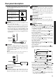
Facilities and connections Remote controller description Note: When you use the buttons that apply to specific mode (i.e., DVD mode, RCVR/Tape mode, or CD mode), you must press the corresponding mode button first. Standby ( ) button This button sets the unit to Standby mode. On ( ) button This button turns on the power to the unit. Scan button Press this button to scan the preset channels. Preset buttons These buttons enable you to select an FM/AM preset channel.
Front panel description This section identifies and explains the controls and displays on the front panel of the DTM-5.3. Front panel Master Volume Standby/On 1 ABC 2 DEF 3 GHI 4 JKL 5 MNO 6 PQR 7 STU 8 VWX 9 YZ- Standby Direct Tuning / 0/10 Scan Speakers B A Clear Zone 2 Direct Display Off Phones DVD Video Memory Tuning FM Mode Character Bass Tape 2 Monitor Tape 1 FM AM Phono Treble Balance CD L R DTM-5.
Front panel description F. TUNED indicator This indicator lights up when the unit receives a radio station signal G. STEREO indicator The indicator lights up when the unit receives an FM stereo radio station signal. H. MEMORY indicator The indicator lights up when you press the Memory button to program a radio station. I. SLEEP indicator This indicator lights up while the Sleep function is active. J.
Rear panel description This section identifies and explains how to use the terminals found on the rear of the DTM-5.3. Before connecting your audio and video components, be sure to read this section carefully and then proceed to the explanations on how to connect each individual component (see page 10).
Rear panel description Depending on the impedance of the speakers used, set the SPEAKER IMPEDANCE SELECTOR on the rear panel as shown in the table. Usable speaker impedance Selector position A or B speaker 4 ohms or higher/speaker A and B speakers 8 ohms or higher/speaker AUDIO IN/OUT There are 6 audio inputs and 3 audio outputs for use with analog signals. The audio inputs and outputs require RCA type connectors.
Connecting components • Do not bind audio connection cables with power cords and speaker cables. Doing so may adversely effect the sound quality. This section explains how to connect the main components to the DTM-5.3 in the standard manner. • Be sure to always refer to the instruction manual that came with the component that you are connecting. • Do not plug in the power cord until all connections have been made.
Connecting components Example of video equipment connections DVD Player (DVD) Monitor TV AUDIO OUTPUT VIDEO OUTPUT VIDEO IN Video Cassette Recorder (VIDEO) ZONE 2 AM A-BUS IR OUT 56K B ZONE 2 OUT DC IN 24V 1A L VIDEO OUT FM 75 SUBWOOFER PRE OUT GND OUT MONITOR OUT DVD IN VIDEO OUT IN IN V OUT IN IN OUT IN L L R R PHONO CD AUDIO IN R REMOTE CONTROL IN AUDIO OUT IR A IN VIDEO IN OUT IR OUT 40K ZONE 2 CONTROL SELECTOR ANTENNA TAPE 1 TAPE 2 DVD VIDEO If there sh
Connecting speakers Connecting the speaker Connecting the speaker cable 1. Strip away 5/8 inch (15 mm) of wire insulation. 2. Twist wire ends very tight. 3. Unscrew. 4. Insert wire. 5. Screw. You can connect two separate pairs of speaker systems. Please connect each speaker according to the illustration, observing the correct connections for R, L, + and –. Check the speaker impedance, then set the SPEAKER IMPEDANCE SELECTOR switch accordingly. Refer to pages 8 and 9 for details.
Connecting antennas To use the tuner of the DTM-5.3, it is necessary to prepare the supplied FM and AM antennas. • Adjustment and placement of the FM and AM antennas for better reception is best performed while listening to a station broadcast. • If better reception cannot be obtained, then placement of an outside antenna is recommended. Assembling the AM loop antenna Connecting an FM outdoor antenna Assemble the loop antenna as shown in the illustration.
Connecting the remote zone (Zone 2) The DTM-5.3 allows you to connect an additional set of speakers and place them in a different room or an area separated for listening to music. This other room or area is referred to as the remote zone (Zone 2), while the room in which the DTM-5.3 is referred to as the main zone. In addition, the IR IN/OUT allows you to control the DTM-5.3 from the remote zone (Zone 2) using the remote controller, even though the remote zone may be physically separated.
main.fm Page 15 Wednesday, April 17, 2002 11:34 AM Operating components not reached by the remote controller signals (IR IN/OUT) The following equipment (sold separately) is essential for operation: • Onkyo’s Multi-Room System kits (IR Remote Controller Extension System), or • Multiroom A/V distribution and control systems from Niles® and Xantech® to name a few. Controlling the DTM-5.3 in the main room from a remote zone (Zone 2) Controlling another component in the main room via the DTM-5.
Connecting the power • Before plugging in the unit, confirm that all connections have been made properly. • Before turning on the power, be sure that the VOLUME knob is fully turned counterclockwise. • Turning on this unit’s power may cause a momentary power surge, which might interfere with other electrical equipment, such as computers. If so, connect the unit to a wall outlet on a different circuit.
Installing the remote controller batteries Installing the batteries 1 Open the battery compartment cover by pushing the tab and opening the cover. Remote controller operation Point the remote controller toward the remote control sensor. The Standby indicator lights up when the unit receives a signal from the remote controller. Remote control sensor DTM-5.3 Standby indicator 2 Insert two AA (R6 or UM-3) batteries into the battery compartment.
Setup and operation Basic operations Master Volume Direct RCVR/Tape Master Volume Standby/On 1 ABC 2 DEF 3 GHI 4 JKL 5 MNO 6 PQR 7 STU 8 VWX 9 YZ- Standby Direct Tuning / 0/10 Scan Speakers B A Clear Zone 2 Off Phones Direct Display DVD Video Tape 2 Monitor Memory Tuning FM Mode Character Bass FM Tape 1 AM Phono Treble Balance SP A / SP B CD R L DTM-5.
Basic operations Listening using the headphones Sleep function (Remote controller only) You can connect stereo headphones with a standard binaural (stereo) plug to the Phones jack. When the headphone plug is inserted, the speakers are not automatically muted but can be controlled using the Speakers A/B buttons. Speakers B A Phones The sleep timer can power off the system after a specified time period. To operate this function, use the remote control supplied with your DTM-5.3.
Receiving stations Please make sure that the T-2 MONITOR and AUDIO MUTE indicators are not lit. For the remote controller, press the RCVR/Tape mode button before performing the procedure in this section.
Receiving stations Number buttons Number buttons RCVR/Tape Master Volume Standby/On 1 ABC 2 DEF 3 GHI 4 JKL 5 MNO 6 PQR 7 STU 8 VWX Memory 9 YZ- Standby Direct Tuning / 0/10 FM Mode Scan Speakers B A Clear Zone 2 Phones Off Direct Display DVD Video Tape 2 Monitor Memory Tuning FM Mode Character Bass Tape 1 FM AM Phono Treble Balance CD R L DTM-5.
Receiving stations Preset ( Scan Number buttons / ) Number buttons RCVR/Tape Scan Master Volume Standby/On 1 ABC 2 DEF 3 GHI 4 JKL 5 MNO 6 PQR 7 STU 8 VWX 9 YZ- Standby Direct Tuning / 0/10 Scan Speakers B A Clear Zone 2 Direct Display Off Phones DVD Video Tape 2 Monitor Memory Tuning FM Mode Character Bass FM Tape 1 AM Phono Treble Balance CD L R DTM-5.
Entering station names Number buttons RCVR/Tape Alphabetic letters/ symbols buttons Tuning DRCT Tune Master Volume Standby/On 1 ABC 2 DEF 3 GHI 4 JKL 5 MNO 6 PQR 7 STU 8 VWX Tuning Down 9 YZ- Standby Direct Tuning / 0/10 Character Scan Speakers Tuning Up B A Clear Zone 2 Direct Display Off Phones DVD Video Tape 2 Monitor Memory Tuning FM Mode Character Bass FM Tape 1 AM Phono Treble Balance CD L R DTM-5.
Recording a source Master Volume Standby/On 1 ABC 2 DEF 3 GHI 4 JKL 5 MNO 6 PQR 7 STU 8 VWX 9 YZ- Standby Direct Tuning / 0/10 Scan Speakers B A Clear Zone 2 Off Phones Direct Display DVD Video Tape 2 Monitor Memory Tuning FM Mode Character Bass Tape 1 FM AM Phono Treble Balance CD L R DTM-5.3 Input selector Input selector buttons Recording an audio source Tape-to-Tape dubbing Please read the instruction manuals concerning operation of each unit.
Recording a source Master Volume Standby/On 1 ABC 2 DEF 3 GHI 4 JKL 5 MNO 6 PQR 7 STU 8 VWX 9 YZ- Standby Direct Tuning / 0/10 Scan Speakers B A Clear Zone 2 Off Phones Direct Display Video DVD Tape 2 Monitor Memory Tuning FM Mode Character Bass Tape 1 FM AM Phono Treble Balance CD L R DTM-5.3 Input selector Input selector buttons Video disc player (or video camcorder) to VCR recording Video disc programs can be recorded onto a VCR (VIDEO).
Using Tape 2 Monitor Master Volume Standby/On 1 ABC 2 DEF 3 GHI 4 JKL 5 MNO 6 PQR 7 STU 8 VWX 9 YZ- Standby Direct Tuning / 0/10 Scan Speakers B A Clear Zone 2 Off Phones Direct Display DVD Tape 2 Monitor Video Memory Tuning FM Mode Character Bass Tape 1 FM AM Phono Treble Balance CD L R DTM-5.
Enjoying music in the remote zone On, Standby Zone 2 indicator Preset / Master Volume Standby/On 1 ABC 2 DEF 3 GHI 4 JKL 5 MNO 6 PQR 7 STU 8 VWX 9 YZ- Standby Direct Tuning / 0/10 Scan Speakers B A Clear Zone 2 Off Phones Direct Display DVD Video Tape 2 Monitor Memory Tuning FM Mode Character Bass FM Tape 1 AM Phono Treble Balance CD L R DTM-5.
Remote controller Using the remote controller On Scan Number buttons Master Volume Standby/On 1 ABC 2 DEF 3 GHI 4 JKL 5 MNO 6 PQR 7 STU 8 VWX RCVR/Tape 9 YZ- Standby Direct Tuning / 0/10 Scan Enter Speakers B A Clear Zone 2 Off Phones Direct Display DVD Video Tape 2 Monitor Memory Tuning FM Mode Character Bass Tape 1 FM AM Phono Treble Balance CD L R DTM-5.3 Standby/On Memory Setting the ID number 3 Turn on the power to the DTM-5.
Controlling other components You can operate an DTM-5.3. -connected Integra/Onkyo CD player, cassette tape deck or DVD player using the remote controller provided with the Controlling an Integra/Onkyo CD player The connector of the Integra/Onkyo compact disc player must be connected to the DTM-5.3. 1 Press the CD button. CD Numeric buttons Disc CD operation buttons 2 Press the / button to turn on the Integra/Onkyo compact disc player. 3 Press the desired operation button.
Controlling other components Controlling an Integra/Onkyo cassette tape deck The connector of the Integra/Onkyo cassette tape deck must be connected to the DTM-5.3. 1 Press the RCVR/Tape button. 2 Press the desired operation button. RCVR/Tape Tape operation buttons 30 : : : : : Plays side A (the side facing the front) of the tape. Stops playback, recording, fast forward or rewinding. Fast forwards the tape. Rewinds the tape. Plays side B (the side facing the rear) of the tape.
Appendix Troubleshooting guide If a problem occurs, while you are using the remote controller, first operate the unit using the front panel controls to confirm that it is not due to a malfunction (or expired batteries) of the remote controller. Trouble Cause Remedy No power. • Power cord is disconnected. • There is external noise in the computer circuits of this unit. • Connect power cord. • Turn the power switch off and then on again, or remove the AC plug from the outlet and then plug it again.
main.fm Page 32 Wednesday, April 17, 2002 11:34 AM Specifications AMPLIFIER SECTION Image Rejection Ratio: 40 dB Power Output: IF Rejection Ratio: 90 dB Signal-to-Noise Ratio Mono: Stereo: 76 dB, IHF 70 dB, IHF 100 Watts per channel, min RMS, at 8 ohms, both channels driven from 20 Hz to 20 kHz, with no more than 0.08% THD. 2 × 170 Watts at 2 ohms 2 × 135 Watts at 4 ohms 2 × 140 Watts at 8 ohms Total Harmonic Distortion: 0.08% at rated power 0.