Contents AV Receiver DTR-6.4/5.4 Before using 2 Facilities and connections 8 Setting up your DTR-6.4/5.4 30 Enjoying Music and Movies (Basic Settings) 36 Instruction Manual Configuring your DTR-6.4/5.4 (Advanced Settings) 52 Thank you for purchasing the AV Receiver. Please read this manual thoroughly before making connections and plugging in the unit. Following the instructions in this manual will enable you to obtain optimum performance and listening enjoyment from your new AV Receiver.
WARNING: TO REDUCE THE RISK OF FIRE OR ELECTRIC SHOCK, DO NOT EXPOSE THIS APPLIANCE TO RAIN OR MOISTURE. CAUTION: TO REDUCE THE RISK OF ELECTRIC SHOCK, DO NOT REMOVE COVER (OR BACK). NO USER-SERVICEABLE PARTS INSIDE. REFER SERVICING TO QUALIFIED SERVICE PERSONNEL.
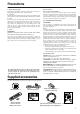
Precautions 1. Recording Copyright Recording of copyrighted material for other than personal use is illegal without permission of the copyright holder. 2. AC Fuse The fuse is located inside the chassis and is not user-serviceable. If power does not come on, contact your Integra/Onkyo authorized service station. 3. Care From time to time you should wipe the front and rear panels and the cabinet with a soft cloth.
Contents Before using Miscellaneous Connections ............................. 28 Precautions.......................................................... 3 Connections for remote control........................................28 RS232 ...............................................................................28 A-BUS ..............................................................................28 12V TRIGGER OUT........................................................28 Supplied accessories ............
Contents Recording ...........................................................50 Operating your programmed remote controller .....68 Recording the input source (Rec Out selector) ................50 Recording both the audio and video ................................51 DVD Mode (DVD Player Mode)..................................... 68 SAT Mode (Satellite Tuner Mode) .................................. 68 Cable Mode (Cable Mode) .............................................. 68 VCR Mode (VCR Mode)...........
Features DTR-6.4 DTR-5.4 Amplifier Features Amplifier Features ■ 100 W × 2 (Front)/ 100 W (Center)/ 100 W × 2 (Surround)/ ■ 85 W × 2 (Front)/ 85 W (Center)/ 85 W × 2 (Surround)/ 85 W ■ ■ ■ ■ ■ ■ 100 W (Surround Back) at 8 ohms, 20 Hz - 20 kHz, 0.08 % THD (FTC rated) Wide Range Amplifier Technology (WRAT) State-of-the-art linear PCM 192 kHz/24-bit DACs for All channels Optimum gain volume circuitry A-BUS Output for Second Zone ■ ■ (Surround Back) at 8 ohms, 20 Hz - 20 kHz, 0.
Before using this unit Connecting the power cord Using the remote controller Plug the supplied power cord into this AC INLET. • Do not use a power cord other than the one supplied with the DTR-6.4/5.4. The power cord supplied is designed for use with the DTR-6.4/5.4 and should not be used with any other device. • Never have the power cord disconnected from the DTR-6.4/5.4 while the other end is plugged into the wall outlet. Doing so may cause an electric shock.
Index parts and facilities Here is an explanation of the controls and displays on the front panel of the DTR-6.4/5.4. DTR-6.4 Front panel DTR-5.
Index parts and facilities For further operational instructions, see the pages indicated in brackets [ ]. Standby/On button [29] If pressed with the Power switch turned on (with the receiver plugged in for US models), the DTR-6.4/5.4 turns on and the display lights up. If pressed again, the DTR-6.4/5.4 returns to the standby state. In the standby state, the display is turned off and the DTR-6.4/5.4 cannot be operated. Standby indicator [7, 29] Lights when the DTR-6.4/5.
Index parts and facilities Rec Out, Zone 2, Off, Level / buttons, and Zone 2 indicator [49, 50] The Rec Out and Zone 2 buttons allow you to use the DTR-6.4/5.4 to output to a remote zone (Zone 2) or to another component for recording (Rec Out). Press the Rec Out button to output the audio signals to a recording component for recording. Press the Zone 2 button to enjoy the output from the DTR-6.4/5.4 in a different room, which is referred to as the remote zone (Zone 2).
Index parts and facilities Rear panel This illustration shows the DTR-6.4 shipped to the North American area. The number and shape of the terminals may be different depending on the model and shipping area. ANTENNA AM FM 75 COMPONENT VIDEO INPUT 2 INPUT 1 ZONE 2 SPEAKERS OUTPUT 12 V TRIGGER OUT Y PB A PR B 56K IR OUT 40K A ZONE 2 OUT DC IN 24V 1A ZONE 2 LINE OUT SURROUND SPEAKERS FRONT SPEAKERS L L R R CENTER SPEAKER AC OUTLETS AC 120 V 60 Hz SWITCHED TOTAL 120W 1A MAX.
Index parts and facilities Remote controller MONITOR OUT VIDEO/S VIDEO [19] These jacks are for connecting to the video input jacks on television monitors or projectors. RC-534M (for DTR-6.4) IR IN/OUT [27] These connectors are for connecting the remote sensor of a multiroom kit (sold separately). PRE OUT ZONE 2 [26] When using the power amplifier for Zone 2 speakers, connect the power amplifier to these terminals.
Index parts and facilities The RC-534M/517M is a multi-functional remote controller. The instructions given here only explain how to use the remote controller in conjunction with the DTR-6.4/5.4. To operate the DTR-6.4/5.4 using the remote controller, first press the RCVR Mode button to place the remote controller in the receiver mode. Send/Learn indicator [7] Lights red when signals are sent by the remote controller. It also flashes when a button is pressed when the battery power is low.
About Home Theater Enjoying Home Theater The DTR-6.4/5.4 has many excellent features to recreate clear three-dimensional sound image and lively sound movement. This enables you to easily enjoy rich sound effects just like you were in a theater or concert hall at home. For the DTR-6.4, Integra recommends you to use the THX-certified THX speaker system for THX Surround EX playback. When playing DVD software, you can enjoy sound effects provided by DTS, Dolby Digital or THX (DTR-6.
AV cables and connectors • Be sure to always refer to the instructions that came with the component that you are connecting. • Do not plug in the power cord until all connections have been properly made. • For input jacks, red connectors (marked R) are used for the right channel, white connectors (marked L) are used for the left channel, and yellow connectors (marked V) are used for video connection. • Insert all plugs and connectors securely.
Connecting speakers For locating speakers, see “About Home Theater” on page 14 and “Surround back speaker placement” on this page. Connect only speakers with an impedance between 6 and 16 Ω to the DTR-6.4/5.4. Connecting speakers with an impedance lower than 6 Ω may damage the amplifier.
Connecting speakers placement angle or the polarity matching for speaker connections is inappropriate, the audio phase displacement occurs. The audio phase displacement may produce obscure sound image, unstable soundfield or sound awkwardness. Layout with dipolar speakers Layout with monopolar speakers 1 1 2 3 2 3 5 4 Connecting the speaker cables After determining the layout of your speaker system, it is now necessary to connect the speakers correctly to your DTR-6.4/5.4. 1. Strip away approx.
Connecting your AV components Here is an explanation of typical ways to connect various components to the DTR-6.4/5.4. There are many ways that any one component can be connected, and it is up to you to decide which method best fits your situation. The directions given here are only one option and should only be thought of as such. It is best to fully understand the nature of each connector and terminal as well as those of your components and their features to ascertain which method of connection is best.
Connecting your AV components 4.
Connecting your AV components Connecting a DVD Player with 2-Channel (L/R) Audio Output ANTENNA AM FM 75 COMPONENT VIDEO INPUT 2 INPUT 1 OUTPUT 12 V TRIGGER OUT Y 56K IR OUT 40K A PB A ZONE 2 OUT DC IN 24V 1A ZONE 2 LINE OUT RS232 Component video output L B R B PR REMOTE CONTROL ZONE 2 IN 2 OPTICAL DIGITAL 1 OUT COAXIAL VIDEO 3 IN VIDEO 2 OUT IN VIDEO 1 OUT IN DVD IN IR MONITOR OUT OPTICAL OUT Video output V IN S video output S * IN COAXIAL IN GND IN IN OUT
Connecting your AV components : Signal flow Component video output Video output ANTENNA 7. Satellite tuner or television (VIDEO 3) AM FM 75 S Video output COMPONENT VIDEO INPUT 2 INPUT 1 OUTPUT 12 V TRIGGER OUT Y 56K IR OUT 40K A PB A ZONE 2 OUT DC IN 24V 1A ZONE 2 LINE OUT RS232 L 6.
Connecting your AV components ANTENNA AM FM 75 COMPONENT VIDEO INPUT 2 8. DVD recorder, other digital video recording device (VIDEO 2) INPUT 1 OUTPUT 12 V TRIGGER OUT Y PB A PR B 56K IR OUT 40K A ZONE 2 OUT DC IN 24V 1A ZONE 2 LINE OUT RS L B Digital audio input (coaxial) IN 2 OPTICAL DIGITAL OUT COAXIAL VIDEO 3 IN VIDEO 2 OUT IN VIDEO 1 OUT IN DVD IN REMOTE CONTROL 1 IR MONITOR OUT OPTICAL OU V DTR-6.
Connecting your AV components Connecting the power cords from other devices The DTR-6.4/5.4 is equipped with AC mains outlet(s) for connecting the power cords from other device(s) so that their power is supplied through the DTR-6.4/5.4. By doing this, you can leave the connected device turned on and have the Standby/On button on the DTR-6.4/5.4 turn on and off the device together with the DTR-6.4/5.4. The shape, number, and total capacity of the AC outlets may differ depending on the area of purchase.
Connecting antennas To use the tuner of the DTR-6.4/5.4, it is necessary to prepare the supplied FM and AM antennas. • Adjustment and placement of the FM and AM antennas for better reception must be done while listening to a station broadcast. • If better reception cannot be obtained, then placement of an outside antenna is recommended. Assembling the AM loop antenna Assemble the loop antenna as shown in the illustration.
Connecting antennas Connecting an FM outdoor antenna Directional linkage Make sure to follow the general rules given below: • Keep the antenna away from noise sources (neon signs, busy roads, etc.). • It is dangerous to put the antenna close to power lines. Keep it well away from power lines, transformers, etc. ANTENNA AM Do not use the same antenna for both FM and TV (or VCR) reception since the FM and TV (or VCR) signals can interfere with each other.
Connecting the remote zone (Zone 2) speakers The DTR-6.4/5.4 allows you to listen to two separate input sources at the same time. This allows you to, for example, place speakers in two different rooms so that two or more people can enjoy two different kinds of music at the same time. The room where the DTR-6.4/5.4 is actually located is referred to as the main room while the separate room is referred to as the remote zone (Zone 2). In addition, the IR IN terminal of the DTR-6.4/5.
Operating components not reached by the remote controller signals (IR IN) In order to use the remote controller to control the DTR-6.4/5.4 from a remote location, you will need to prepare a multi-room kit (sold separately) such as one of those given below: • Onkyo’s Multi-Room System kit (IR Remote Controller Extension System) • Multiroom A/V distribution and control system such as those from Niles® and Xantech® Make the connections as shown below.
Miscellaneous Connections Connections for remote control The terminal on the DTR-6.4/5.4 is for connecting other Integra/Onkyo components equipped with the same terminal. When a component is connected to the terminal, it can be operated by the remote controller supplied with the DTR-6.4/5.4. In addition, when you connect a component to the terminal, you can also perform the system operations given below. Power on/ready function When the DTR-6.4/5.
Connecting the power Diagram for DTR-6.4 Diagram for RC-534M Standby/On Standby indicator RC-534M On Standby RCVR Mode CH VOL Disc Audio Sel Muting A Subtitle M Angle TV / VCR Level Random Audio Adjust Rec Input Selector DVD To wall outlet CD V1 V2 TAP V3 V4 V5 PH 1 2 3 Pure A Direct Stereo 4 5 6 SURR THX All ST 7 DSP 8 DSP 9 Re-EQ +10 0 Search Display Dimmer Zone 2 -- / --- • Before you plug in the DTR-6.4/5.
Setup Menu When making the various settings required to configure your DTR-6.4/5.4 for optimum performance, you can either use the OSD Menu that appears on your television monitor or you can use the display on the front of the DTR-6.4/5.4. The OSD Menu is a settings menu that is displayed on your TV monitor. For your reference when performing the setting procedures, this manual shows both the OSD Menu displayed on your television monitor and the display on the front of the DTR-6.4/5.4.
Setup Menu RC-534M / / / Setup Return Return Setup CH VOL Disc Audio Sel Muting A Subtitle M Angle TV / VCR Level Random / / / ENTER Audio Adjust Rec Input Selector DVD CD V1 V2 TAP V3 V4 V5 2 3 Direct Stereo 4 5 6 SURR THX All ST 7 Buttons used for navigating through the menus You can change settings in the Setup Menu using the buttons on the front panel and on the remote controller. The buttons on the remote controller correspond to those on the DTR-6.4/5.
Selecting the appropriate setting for your connection RC-534M / / / Setup Return Return Setup CH VOL Disc Audio Sel Muting A Subtitle M Angle TV / VCR Level Random / / / ENTER Audio Adjust Rec Input Selector DVD CD V1 V2 TAP V3 V4 V5 2 3 Direct Stereo 4 5 6 SURR THX All ST 7 Hardware Config In this section, you will perform the initial settings for following scenarios.
Selecting the appropriate setting for your connection • If “Small” is selected for the Front setting, “Large” cannot be selected for this setting. Speaker Configuration To create the optimum sound space for both visual and audio pleasure, it is necessary to set which type and size of speakers you will use. Once made, you will not need to change these settings unless you change the speaker configuration.
Selecting the appropriate setting for your connection DTR-5.4 This setting allows you to set the crossover frequency for your speaker system. The crossover frequency is the minimum frequency delivered to a speaker and can be set to 60 Hz, 80 Hz, 100 Hz, 120 Hz, or 150Hz. This setting is valid when “Subwoofer” is set to “Yes,” or for speakers that are set to “Small,” at the “Speaker Config” menu.
Selecting the appropriate setting for your connection RC-534M Return Setup Return Setup CH VOL Disc Audio Sel Muting A Subtitle M Angle TV / VCR Level Random / / / ENTER Audio Adjust Rec Input Selector DVD Input Selector buttons Tape / / / Input source buttons 3. Use the and cursor buttons to select “5. Input Setup” and then press the Enter button. The “Input Setup” menu appears. * Menu ***************** 1.Speaker Config 5.Input Setup 2.Speaker Distance******* ****Input:DVD 3.
Enjoying music or videos with the DTR-6.4/5.4 DTR-6.4 RC-534M Light* (DTR-6.4 only) RCVR Mode CH VOL VOL Disc Audio Sel Muting A Subtitle M Angle TV / VCR Level Random Audio Adjust Rec Input Selector DVD CD V1 V2 TAP V3 V4 V5 Input source buttons Though the DTR-6.4/5.4 is often used to listen to the radio, it does not show you its true ability until it is used to play music or watch videos, DVDs, and the like. The DTR-6.4/5.
Enjoying music or videos with the DTR-6.4/5.4 RC-534M Sleep Dimmer CH VOL Disc Audio Sel Muting A Subtitle M Angle TV / VCR Level Random Muting Audio Adjust Rec Input Selector DVD CD V1 V2 TAP V3 V4 V5 2 3 Direct Stereo 4 5 6 SURR THX All ST 7 To turn off the sound momentarily, press the Muting button on the remote controller. The Muting indicator will flash and the sound from the speakers or headphones will be switched off by the receiver’s audio muting circuit.
Enjoying music or videos with the DTR-6.4/5.
Enjoying music or videos with the DTR-6.4/5.4 RC-534M Preset / Cursor CH Audio Sel / VOL Disc Audio Sel Muting A Subtitle M Angle TV / VCR Level Random Audio Adjust Rec Input Selector DVD CD V1 V2 TAP V3 V4 V5 2 3 Direct Stereo 4 5 6 SURR THX All ST 7 Press the Audio Selector button on the front panel (or Audio Sel button on the remote controller) to change the audio mode.
Enjoying DVD multichannel audio playback Direct/Pure Audio (DTR-6.4) Surround (DTR-6.4) Stereo (DTR-5.4) RC-534M Surround (DTR-5.
Enjoying DVD multichannel audio playback To turn off the tone control: Press the Direct button. DTR-6.4 Remote controller DTR-5.4 2 Direct “Direct” appears on the display and the tone control is turned off. Changing the listening mode (DTR-6.4 only) Each time you press the Direct/Pure Audio button on the front panel, the display changes between “Direct” “Pure Audio.” When using a remote controller, press Pure A or Direct button. DTR-6.
Listening to Radio Broadcasts FM Mode Tuning / Tuner One of the features of the DTR-6.4/5.4 that is most frequently used is its ability to play FM and AM broadcast radio stations. The DTR6.4/5.4 provides a number of listening modes perfect for listening to the radio and getting the most out of your audio system. Also, by presetting radio stations that you listen to frequently, you can select them easily by pressing the CH button on the remote controller. Tuning into a radio station 4.
Listening to Radio Broadcasts FM Mode Memory Preset RC-534M / RCVR Mode CH CH VOL Disc Audio Sel Muting A Subtitle M Angle TV / VCR Level Random Audio Adjust Rec Input Selector CD DVD V2 TAP V3 V4 V5 2 3 Direct Stereo 7 DSP Tuner PH 1 SURR 5 THX 8 DSP 6 All ST 9 Re-EQ +10 0 Search Display Dimmer Zone 2 -- / --- TUN TUN Pure A 4 Enter Presetting a radio station V1 Enter Selecting a preset radio station 1.
Listening Modes The DTR-6.4/5.4’s surround sound enables you to enjoy the presence of a movie theater or concert hall in your room. The configuration of the speakers is very important for the surround sound. Refer to “About Home Theater” on page 14. Before using a listening mode, make sure the Speaker Config has been set (see page 33). Once the parameters have been set, it is not necessary to set them again.
Listening Modes • THX Surround EX “THX Surround EX - Dolby Digital Surround EX” is a joint development of Dolby Laboratories and the THX division of THX Ltd. In a movie theater, film soundtracks that have been encoded with Dolby Digital Surround EX technology are able to reproduce an extra channel which has been added during the mixing of the program.
Listening Modes DTR-6.4 RC-534M Listening mode buttons RCVR Mode CH VOL Disc Audio Sel Muting A Subtitle M Angle TV / VCR Level Random Audio Adjust Rec Input Selector DVD CD V1 V2 TAP V3 V4 V5 2 3 Pure A Direct Stereo 4 7 DSP Tip: You can set in advance a different listening mode for each input source. For more details, see page 57. When using the remote controller, first press the RCVR Mode button before preceding to the step below.
Listening Modes DTR-5.4 RC-517M Listening mode buttons RCVR Mode CH VOL Disc Audio Sel Muting A Subtitle M Angle TV / VCR Level Random Audio Adjust Rec Input Selector DVD CD V1 V2 TAP V3 V4 V5 1 2 Pure A Direct 4 SURR • Refer to pages 44 and 45 for more details of listening modes. • Refer to page 45 for sources and listening modes. • When playing Dolby Digital or DTS software, the listening mode will automatically change to Dolby Digital or DTS.
Listening Modes Surround (DTR-6.4) RC-534M Surround (DTR-5.4) THX (DTR-6.4) RCVR Mode CH VOL Disc Audio Sel Muting A Subtitle M Angle TV / VCR Level Random Audio Adjust Rec Input Selector DVD SURR CD V1 V2 TAP V3 V4 V5 • While playing back DTS sources Each time you press the SURR button, the DTS-ES setting switches from: Auto → On → Off. Auto: When a DTS source with a DTS-ES flag (ID signal for DTS-ES) is input, the listening mode changes automatically to DTS-ES Discrete 6.
Enjoying music in the remote zone Zone 2 indicator Off RC-534M On/Standby Level / CH VOL Disc Audio Sel Muting A Subtitle M Angle TV / VCR Level Level / Random Audio Adjust Rec Input Selector DVD CD V1 V2 TAP V3 V4 V5 2 3 Direct Stereo 4 5 6 7 Input source buttons Using the buttons 1. Press the Zone 2 button. 2. Select an input source. After pressing the Zone 2 button, you must press an input source button within 5 seconds. The Zone 2 indicator lights. Ex.
Recording Rec Out Off Input source buttons Notes: • You cannot record the surround effects. • Digital signals input to the DIGITAL IN jacks will be output to the DIGITAL OUT jacks. • There are some restrictions on recording digital signals. When making digital recordings, consult the instruction manual that came with your digital recording equipment (e.g., MD recorder or DAT deck) to know what restrictions are imposed. • You cannot record the source connected to the 5.1-channel input jacks.
Recording Recording both the audio and video The DTR-6.4/5.4 also allows you to record the audio and video signals output from the VIDEO OUT 1 and 2 jacks. 1. Press the input source button for the source you want to record. 2. Start recording at the recording device connected to the VIDEO OUT 1 and 2 jacks. Note: Be aware that if you change the input source that you are watching (or listening to), the selected source will be recorded.
Configuring the speakers (DTR-6.4) RC-534M / / / Setup Return Return Setup CH VOL Disc Audio Sel Muting A Subtitle M Angle TV / VCR Level Random / / / ENTER Audio Adjust Rec Input Selector DVD CD V1 V2 TAP V3 V4 V5 2 3 Direct Stereo 4 5 6 SURR THX All ST 7 Setting the speaker distance from your normal listening position Set the distance between the listening position and the speakers.
Configuring the speakers (DTR-6.4) (4) Repeat steps (2) and (3) above for the front right and other speakers until all speakers are adjusted to the same volume level. Calibrating the speaker levels Use this menu to set the volume for each speaker so that each volume is heard by the listener at the same level. This is especially important for speaker layouts where the left and right speakers are at different distances or in asymmetrical positions due to room designs and configurations.
Configuring the speakers (DTR-5.4) RC-517M / / / Setup Return Return Setup CH VOL Disc Audio Sel Muting A Subtitle M Angle TV / VCR / / / ENTER Level Test Random Audio Adjust Rec Input Selector DVD CD V1 V2 TAP V3 V4 V5 2 3 Direct Stereo 4 5 6 SURR THX All ST 7 Setting the speaker distance from your normal listening position Set the distance between the listening position and the speakers.
Configuring the speakers (DTR-5.4) Press the Setup button on the front panel or on the remote controller button to exit the Setup menu. Calibrating the speaker levels Use this menu to set the volume for each speaker so that each volume is heard by the listener at the same level. This is especially important for speaker layouts where the left and right speakers are at different distances or in asymmetrical positions due to room designs and configurations.
Input Setup RC-534M Return Setup Return Setup CH VOL Disc Audio Sel Muting A Subtitle M Angle TV / VCR Level Random / / / ENTER Audio Adjust Rec Input Selector Input Selector buttons / / / Input source buttons Adjusting the volume differences between components (Intelligent Volume) This setting allows you to adjust for the volume differences between your various input source components.
Input Setup Configuring the listening modes frequently you use You can preset the listening mode for individual input source. The listening mode will be reset to the mode you set here after turning on the DTR-6.4/5.4 even if you change the listening mode using the Listening Mode buttons. 1. Select the desired input source. 2. Press the Setup button on the front panel or on the remote controller to display the main menu on the monitor and the front display. The main menu appears. g. D. F.
Preference Adjusting the headphones volume level You can adjust the volume output from the headphones so that it matches the level output from the speakers. 1. Display the main menu. Press the Setup button on the front panel or the remote controller to display the main menu on the monitor and the front display. 2. Use the and cursor buttons to select “6. Preference” and then press the ENTER button. The “Preference” menu appears. DTR-6.4/5.4 * Menu ***************** 1.Speaker Config 6.Preference 2.
Audio Adjust RC-534M Audio Adjust CH VOL Disc Audio Sel Subtitle M Angle Level Random Audio Adjust Rec Input Selector DVD V2 V3 Setup Procedure 1. Press the Audio Adjust button. The Audio Adjust settings appear in the front display and on the monitor. Bass Treble : : 0dB 0dB Note: The items that appear in the menu depend on the currently selected listening mode or the input signal. 2. Use the and cursor buttons to select the item that you want to set. 3.
Audio Adjust Setting available when you play mono, 2-channel or 96 kHz format signal Double Bass The Double Bass function boosts the bass sound by letting the bass sound of “Front L/R” speakers output also from the subwoofer. To enable this function, in the “Speaker Config” menu, set the “Subwoofer” to “Yes” and “Front L/R” to “Large.” Note: Double Bass “Off” is the THX preferred setting for accurate bass reproduction. On: Select to turn on the Double Bass function.
Audio Adjust Reverb Level This setting allows you to adjust the depth of acoustic reverberation to match the playback source material, the acoustics of your room, and such other factors. Select from the three settings “Low,” “Mid,” and “High.” Reverb Time Adjust the reverb time to match the source being played back and the acoustics of the room. Select from the three settings “Short,” “Mid,” and “Long.” Settings available when you play monaural signal Academy Filter (DTR-6.
Using remote controller Overview The RC-534M/517M remote controller is a useful tool that can not only operate the DTR-6.4/5.4, but also all the other components of your home theater as well. To operate any component, first press the Mode button on the remote controller that corresponds to the component that you wish to control. Then simply press the desired operation button and the component will operate accordingly. For example, if you wish to select the CD input source at the DTR-6.4/ 5.
Using remote controller Controlling an Integra/Onkyo DVD player The connector of the Integra/Onkyo DVD player must be connected to the DTR-6.4/5.4 (see page 28). 1. Press the DVD Mode button. The DVD Mode button lights. 2. Press the desired operation button. The buttons shaded in the figure to the left are the operation buttons that can be used to control an Integra/Onkyo DVD player.
Using remote controller Controlling an Integra/Onkyo CD player The connector of the Integra/Onkyo compact disc player must be connected to the DTR-6.4/5.4 (see page 28). 1. Press the CD Mode button. RC-534M On Standby The CD Mode button lights. 2. Press the desired operation button. The buttons shaded in the figure to the left are the operation buttons that can be used to control an Integra/Onkyo compact disc player.
Using remote controller Controlling an Onkyo MD recorder The connector of the Onkyo MD recorder must be connected to the DTR-6.4/5.4 (see page 28). 1. Press the SAT/MD Mode button. The SAT/MD Mode button lights. 2. Press the desired operation button.
Entering a pre-programming code The remote controller has three learning functions. One is entering the pre-programmed code for a remote controller of another manufacturer. Another is the normal learning function that enables the remote controller to learn the codes directly from other remote controllers (see page 70).
Entering a pre-programming code VCR Pre-programming codes Note: If more than one code is given in the table, try each code one by one until you reach the code that works (i.e. if the first code does not work, then try the next). DVD BRAND DENON HITACHI JVC KENWOOD MAGNAVOX MARANTZ MITSUBISHI INTEGRA/ONKYO PANASONIC PIONEER PROSCAN RCA SONY TOSHIBA YAMAHA ZENITH SETTING No.
Operating your programmed remote controller After entering a pre-programming by following the procedure given above, the following modes become enabled for use. DVD Mode (DVD Player Mode) Operations are the same as explained on page 63. SAT Mode (Satellite Tuner Mode) 1. Press the SAT/MD Mode button. The SAT/MD Mode button lights. RC-534M On Standby 2. Press the desired operation button.
Operating your programmed remote controller VCR Mode (VCR Mode) 1. Press the VCR Mode button. The VCR Mode button lights. 2. Press the desired operation button.
Programming the commands of remote controllers for other devices into the remote controller E AP VD T D P U O R D D C ER W PO D VD VID EO TA P EE SL IS C G -2 EO VID P IN PE ER M IM D -1 D C CH TI- T UL PU M IN RE SUOD M O N R O T TO H SE C P ER E LE R N PR SE E TU T N U TU C H SE L ST E TEON T U M TIN G VO LU E M S 85 Programming procedure 2 to 6 inches (5 to 15 cm) When programming the commands of another remote controller to the RC-534M/517M remote controller, you mu
Programming the commands of remote controllers for other devices into the remote controller 4. Press and hold down the button (that corresponds to the command you are programming) on the remote controller of the other device until the Send/Learn lamp on the remote controller flashes twice. After flashing twice, the Send/Learn indicator will light again. 5.
Using the macro function What is the macro function? A macro function enables you to program a series of button operations (up to 16) on the remote controller into a single button. The series of operations are then called a macro. For example, to play a compact disc player connected to the DTR-6.4/5.4 normally, you must perform the following steps: 1. Press the RCVR Mode button. 2. Press the On button.
Using the macro function Erasing a macro from the Macro 1 (or 2) button Send/Learn indicator 1. Press and hold down any one of the seven Mode buttons, press the Macro 1 (or 2) button, and then release both buttons. RC-534M Macro 1 Macro 2 Mode buttons When you press the Mode button, it lights and the Send/Learn indicator lights. When you press the Macro 1 (or 2) button, the indicator turns off. When you release the buttons, the indicator flashes once. 2. Press the Macro 1 (or 2) button again.
Specifications (DTR-6.4) AMPLIFIER SECTION Continuous average power output (FTC) All channels: 100 W per channel min. RMS at 8 Ω, 2 channels driven from 20 Hz to 20 kHz with no more than 0.08% total harmonic distortion. 125 W min. RMS at 6 Ω, 2 channels driven from 1 kHz with no more than 0.1% total harmonic distortion.
Specifications (DTR-5.4) AMPLIFIER SECTION Continuous average power output (FTC) All channels: 85 W per channel min. RMS at 8 Ω, 2 channels driven from 20 Hz to 20 kHz with no more than 0.08% total harmonic distortion. 110 W min. RMS at 6 Ω, 2 channels driven from 1 kHz with no more than 0.1% total harmonic distortion.
Troubleshooting guide If a problem occurs while you are using the remote controller, first try to operate the controls on the front panel of the DTR-6.4/5.4 to make sure that it is not due to a malfunction (or worn out batteries) in the remote controller. POWER No power. • Power cord is disconnected. ➞ Connect the power cord (see pages 7 and 29). • External noise is affecting the internal microcomputer. ➞ Turn off the power, wait five seconds, and then turn back on the power. • Internal fuse is blown.
Troubleshooting guide Stereo indicator lights, but sound is distorted and stereo separation is bad. • Station is too strong. ➞ Change to FM indoor antenna (see page 24). • Multiple reflection of the radio waves because of tall buildings or mountains. ➞ Use antenna that has better directivity and orient it so distortion is least. Indicators for stereo reception flicker and hiss is heard on FM stations. • Station is too weak. ➞ Install an outdoor FM antenna (see page 25).
Troubleshooting guide If one of the messages shown below appears “Not available with headphones use” Operation not allowed because headphones are plugged into the DTR-6.4/5.4. “Not available with Multichannel use” Operation not allowed while the multi-channel output is being used. “Not available in this Sp Config” Will not work with the current speaker configuration settings. “Not available in Zone 2 mode” Setting not allowed because the Zone 2 mode is turned on.
Memo 79
Integra Division of ONKYO U.S.A. CORPORATION 18 Park Way, Upper Saddle River, N.J. 07458, U.S.A. Tel: 201-785-2600 Fax: 201-785-2650 http://www. integrahometheater.com Integra Division of ONKYO CORPORATION Sales & Product Planning Div. : 2-1, Nisshin-cho, Neyagawa-shi, OSAKA 572-8540, JAPAN Tel: 072-831-8111 Fax: 072-831-8124 SN 29343499 © copyright 2003 ONKYO CORPORATION Japan. All rights reserved.