Contents AV Receiver Before using 2 Facilities and connections 8 DTR-6.2 Instruction Manual Thank you for purchasing the AV Receiver. Please read this manual thoroughly before making connections and plugging in the unit. Following the instructions in this manual will enable you to obtain optimum performance and listening enjoyment from your new AV Receiver. Please retain this manual for future reference.
WARNING: TO REDUCE THE RISK OF FIRE OR ELECTRIC SHOCK, DO NOT EXPOSE THIS APPLIANCE TO RAIN OR MOISTURE. CAUTION: TO REDUCE THE RISK OF ELECTRIC SHOCK, DO NOT REMOVE COVER (OR BACK). NO USER-SERVICEABLE PARTS INSIDE. REFER SERVICING TO QUALIFIED SERVICE PERSONNEL.
21. Replacement Parts – When replacement parts are required, be sure the service technician has used replacement parts specified by the manufacturer or have the same characteristics as the original part. Unauthorized substitutions may result in fire, electric shock, or other hazards. 22. Safety Check – Upon completion of any service or repairs to the appliance, ask the service technician to perform safety checks to determine that the appliance is in proper operation condition. 23.
Contents Before using Connecting the AM antenna cable ................................. 22 Important Safeguards ......................................... 2 Connecting the included antennas ................................. 22 Precautions ......................................................... 3 Connecting an FM outdoor antenna ............................... 23 Contents .............................................................. 4 Connecting an AM outdoor antenna ..............................
Contents 2-1. Audio Setup sub-menu ............................................ 38 Operationing your programmed remote controller ...................................................... 52 2-2. Video Setup sub-menu ............................................ 39 DVD MODE (DVD Player Mode) ................................ 52 2-3. Listening Mode Preset sub-menu ........................... 40 SAT MODE (Satellite Tuner Mode) .............................. 52 2-4. IntelliVolume sub-menu ...................
Features Amplifier Features ■ 5.1-Channel input ■ 100 Watts minimum of continuous RMS power to each of the five channels into 8 Ω from 20 Hz to 20 kHz with no more than 0.
Before using this unit Installing the remote controller batteries 1. Remove the battery compartment cover by pressing and sliding the cover. 2. Insert two AA (R6 or UM-3) batteries into the battery compartment. Carefully follow the polarity diagram (positive (+) and negative (–) symbols) inside the battery compartment. Using the remote controller Point the remote controller toward the remote control sensor. The STANDBY indicator lights up when the unit receives a signal from the remote controller.
Front panel facilities Here is an explanation of the controls and displays on the front panel of the DTR-6.2.
Front panel facilities For operational instructions, see page indicated in brackets [ ]. Power switch [21] Turns on and off the main power supply for the DTR-6.2. Standby indicator [7, 21] Lights when the DTR-6.2 is in the standby state and flashes when a signal is received from the remote controller. Standby/On button [21] Press to turn on the DTR-6.2 when in the standby state. Press again to return the DTR-6.2 to the standby state.
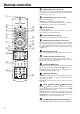
Remote controller SEND/LEARN indicator [50, 54, 56] This indicator acts as a guide when commands are programmed into or sent by the remote controller. It also warns the user when an error is made or battery power is low. 1 ON/STDBY button [21, 47-50, 52, 53, 60] ON: Turns on the DTR-6.2. STDBY: Places the DTR-6.2 in the standby state. Be aware that pressing the STDBY button only places the DTR-6.2 in standby and does not turn the power completely off.
Remote controller INPUT SELECTOR buttons [28, 29, 45, 46, 49] Selects an input source. Same as the input selector buttons on front panel of the DTR-6.2. The input source for each buttons is given here. DVD:DVD, CD:CD, V1:Video1, V2:Video2, V3:Video3, V4:Video4, T1:Tape, T2:Not used with the DTR-6.2, TUN:FM/AM, PH:Phono. Numeric key/Listening mode selector/SP A, B/ Re-EQ/DISPLAY/DIMMER buttons 1 to 9, +10, --/---, 0: For entering the number of a track. [47-50, 52, 53] STEREO, DIRECT, DSP / , SURR, A.
Connections Here is explanation of how to connect the main components to the DTR-6.2 in the standard manner. There are many ways that any one component can be connected, and it is up to you to decide which method best fits your situation. The directions given here are only one option and should only be thought of as such. It is best to fully understand the nature of each connector and terminal as well as each of your components and their features to ascertain which method of connection is best.
Connections : Signal flow Audio connection cable Analog audio output L(White) L R(Red) R L (White) R (Red) 2. CD player (CD) 12 V TRIGGER ANTENNA Digital audio output (optical) COMPONE Y PB PR Y OUT IN A AM INP OUTPUT IN Analog audio output MONITOR OUT FM 75 PHONO R (Red) DVD VIDEO 1 REMOTE CONTROL L (White) 1.
Connections CR/PR Y CB/PB Component video output CB/PB COMPONENT VIDEO Y PB Y PR PB Y PR PB Component video output PR CR/PR Y INPUT 1 OUTPUT OUT IN Video output IN INPUT 2 OUT IN IN V IN Video output VIDEO MONITOR OUT 4.
Connections If the video connection is made at COMPONENT VIDEO INPUT 2, this must be changed at the Setup menu: Input Setup → Video Setup → Component Video (see pages 26, 38). Using an RCA-type audio connection cable, connect the audio output terminal on the device to the audio DVD IN jacks on the DTR-6.2. Make sure that you properly connect the left channel to the L jack and the right channel to the R jack.
Connections Connect to devices with z terminals The z terminal on the DTR-6.2 is for connecting other Integra/ Onkyo components equipped with the same z terminal. When a component are z-connected, you can point the remote controller supplied with the DTR-6.2 at the sensor on the DTR-6.2 and operate that component without having to switch remote controllers. In addition, by connecting components to the z terminal, you can also perform the system operations given below. Power on/ready function When the DTR-6.
Connections Connect to devices with multichannel output By connecting a DVD player, MPEG decoder, or other component that has a multi channel port, you can playback the audio with 5.1 channel output. So, be sure to prepare a cable that can properly connect the DTR-6.2 to the peripheral device.
Connecting speakers Front right speaker 12 V TRIGGER ANTENNA Front left speaker FRONT SPEAKERS COMPONENT VIDEO Y PB Y PR PB Y PR PB Surround right speaker PR SURROUND SPEAKERS CENTER SPEAKER L R Surround left speaker L R A AM INPUT 1 OUTPUT IN OUT IN OUT INPUT 2 IN IN IN VIDEO B MONITOR OUT FM 75 DVD VIDEO 1 VIDEO 2 VIDEO 3 VIDEO 4 AC OUTLETS REMOTE CONTROL AC 120 V 60 Hz SWITCHED TOTAL 120 W 1 A MAX.
Listening to music in the remote zone When using the ZONE 2 SPEAKERS terminals Connect the speaker cables from the speakres in the remote zone (Zone 2) speaker terminals on the DTR-6.2. With this connection, select “Activated” for the Preference → Powered Zone 2 Setup setting in the Setup menu. When using the ZONE 2 OUT terminals The ZONE 2 OUT terminal is a constant output. Connect to the LINE input of the amplifier (CD, tape, etc.).
Operating components not reached by the remote controller signals (IR IN/OUT) The following equipment (sold separately) is essential for operation: • Onkyo’s Multi-Room System kits (IR Remote Controller Extension System), or • Multiroom A/V distribution and control systems from Niles® and Xantech® to name a few Make connection as shown below. Do not plug the equipment into the power source until the connection is complete.
Connecting the power SEND/LEARN indicator ON Standby indicator STDBY Standby/On RCVR MODE Standby/On Rec Out Zone 2 Zone 2 Level DSP/ Mode ADJ CH Level Master Volume MUTING Setup Standby Return Power Push To Enter On Of f Display Phones Power Audio Selector FM Mode Preset Memory Video 1 Dimmer Video 2 Video 3 VCR 1 VCR 2 Tuning Smart Scan Navigator Preset Bass DVD Video 4 Tape FM AM Phono Treble CD To wall outlet HOME THEATER CONTROLLER RC-441M • The DTR-6.
Connecting antennas To use the tuner of DTR-6.2, it is necessary to prepare the supplied FM and AM antennas. • Adjustment and placement of the FM and AM antennas for better reception must be done while listening to a station broadcast. • If better reception cannot be obtained, then placement of an outside antenna is recommended. Assembling the AM loop antenna Assemble the loop antenna as shown in the illustration. • Refer to “Connecting the AM loop antenna” below for details on connecting the loop antenna.
Connecting antennas Connecting an FM outdoor antenna Please make sure that you follow the considerations: • Keep the antenna away from noise sources (neon signs, busy roads, etc.). • It is dangerous to put the antenna close to power lines. Keep it well away from power lines, transformers, etc. • To avoid the risk of lightning and electrical shock, grounding is necessary. Follow item 14 of the “Important Safeguards” on page 2 when you install the outdoor antenna.
Speaker setup After you have installed the DTR-6.2, connected all the components, and determined the speaker layout, it is now time to perform the settings in the Speaker Setup menu for the optimum sound acoustics for your environment and speaker layout. Before you perform the following settings, it is important that you first determine the following characteristics: • The types and sizes of the speakers that are connected. • The distance from each speaker to your normal listening position.
Speaker setup DSP / Mode ADJ 5. Press the jog once and then turn it to set the size of your front speakers. Large: Select if the front speakers are large sized. Small: Select if the front speakers are small sized. Speaker Distance submenu Push To Enter DSP / Mode ADJ Push To Enter This submenu provides settings that tell the DTR-6.2 how far away your speakers are located from the listening position so that it can provide the optimum sound space.
Speaker setup Level Calibration submenu About the other settings This submenu allows you to set the volume levels of each speaker individually so that they all sound at the same level when heard from the listening position. If you are continuing from setting the speaker distances and are still in the setting mode, skip directly to step 2. Note: This setting cannot be made when Zone 2 is turned on, so be sure to put Zone 2 in the standby mode. Setup 1. Press the Setup button. If a menu other than “1.
Listening to Radio Broadcasts FM Mode Standby/On Rec Out Zone 2 Zone 2 Level DSP/ Mode ADJ CH Level Master Volume Setup Standby Return Power Push To Enter On Of f Display Phones Audio Selector Dimmer FM Mode Preset Memory Video 1 Video 2 Video 3 VCR 1 VCR 2 Tuning Smart Scan Navigator Preset Bass DVD Video 4 Tape FM AM Phono Treble CD FM AM Tuning One of the features of the DTR-6.2 that is most frequently used is its ability to play FM and AM broadcast radio stations.
Listening to Radio Broadcasts Jog dial Preset Memory Preset RCVR MODE CH Standby/On Rec Out Zone 2 Zone 2 Level CH Level Master Volume MUTING Setup DSP/ Mode ADJ Standby Return Power Push To Enter On Of f Display Phones Audio Selector Dimmer FM Mode Preset Memory Video 1 Video 2 Video 3 VCR 1 VCR 2 Tuning Smart Scan Navigator Preset Bass DVD Video 4 Tape FM AM Phono Treble CD TUN FM AM HOME THEATER CONTROLLER RC-441M Presetting a radio station Selecting a preset radio
Enjoying music or videos with the DTR-6.
Enjoying music or videos with the DTR-6.
Enjoying music or videos with the DTR-6.
Using listening mode The DTR-6.2’s surround sound enables you to enjoy the presence of a movie theater or concert hall in your room. The configuration of the speakers are very important for the surround sound. Refer to “Connecting speakers” on page 17. Before using a listening mode, make sure the Speaker Setup parameters have been set (refer to page 24-26). Once the parameters have been set, it is not necessary to set them again.
Using listening mode Jog dial Standby/On Rec Out Zone 2 Zone 2 Level DSP/ Mode ADJ CH Level Master Volume MUTING Setup Standby Return Power Push To Enter On Of f Display Phones Audio Selector Dimmer FM Mode Preset Memory Video 1 Video 2 Video 3 VCR 1 VCR 2 Tuning Smart Scan Navigator Preset Bass DVD Video 4 Tape FM AM Phono Treble CD Listening mode buttons Re-EQ HOME THEATER CONTROLLER RC-441M Changing the listening mode To change the listening mode during playback, pres
Setup menus When making the various settings required to configure your DTR6.2 optimally, you can either use the OSD menu that appears on your television monitor or you can use the display on the front of the DTR-6.2. The OSD menu is a settings menu that is displayed on your TV monitor. For use as reference when performing the setting procedures, this manual shows both the OSD menu displayed on your television monitor and the display on the front of the DTR-6.2.
Setup menus Navigating through the Setup menu The explanations here assume you are using the buttons on the remote controller when entering the Setup menu. However, you can use the buttons on the DTR-6.2 as well. When using the buttons on the DTR-6.2, refer to the table on the right and pages 24 to 26. In addition to the display of the Setup menu on your television monitor, the corresponding menu will also be displayed in the front display on the DTR-6.2.
Setup menus 1. Speaker Setup menu 1-1. Speaker Config sub-menu The settings here are also explained on pages 24 to 26. Refer to those pages for reference. 1.Speaker 1.Speaker Setup Setup 2.Input Setup 3.Listening Mode Setup 4.Preference 1.Speaker Config 1-1.Speaker Config 5.OSD Setup Distance 2.Speaker 3.Level Calibration 4.Bass Peak Level a.Subwoofer :Yes b.Front :Large c.Center :Large |ENTER| Quit:|OSD| d.Surround :Large Menu 1.Speaker 1.Speaker Setup Setup 2.Input Setup 3.Listening Mode Setup 4.
Setup menus 1-2. Speaker Distance sub-menu Menu 1.Speaker Setup 1.Speaker Setup 2.Input Setup 3.Listening Mode Setup 4.Preference 1-2.Speaker Distance 1.Speaker 5.OSD Setup Config 2.Speaker Distance 3.Level Calibration a.UnitPeak Level:feet 4.Bass b.Front L/R :12ft c.Center :12ft |ENTER| Quit:|OSD| d.Surround L/R : 7ft |ENTER| Quit:|OSD| Quit:|SETUP| Here you will enter the distance from each speaker to your normal listening position.
Setup menus 2. Input Setup menu This menu allows you to setup the various input sources available with the DTR-6.2. Each input source may have a great number of settings that are difficult to keep track of, so we recommend making a chart to record what you have set and for which component to prevent confusion later. Menu 1.Speaker Setup 2.Input Setup Setup 2.Input Input:DVD 3.Listening Mode Setup 4.Preference 1.Audio Setup 5.OSD Setup 2.Video Setup 3.Listening Mode Preset 4.IntelliVolume 5.
Setup menus 2-2. Video Setup sub-menu Menu Menu 1.Speaker Setup 2.Input Setup Setup 2.Input Input:DVD 3.Listening Mode Setup 4.Preference 2-2.Video Setup a.Audio Setup 5.OSD Setup Input:DVD b.Video Setup c.Listening Mode Preset a.Component Video d.Tone Control :Input1 e.IntelliVolume f.12V Trigger |ENTER| Quit:|OSD| |ENTER| Quit:|OSD| Quit:|SETUP| a. Component Video If a component is connected to the one of the COMPONENT VIDEO inputs (1 or 2), then that input must be set here.
Setup menus 2-4. IntelliVolume sub-menu 2-5. 12V trigger sub-menu Menu Menu 1.Speaker Setup 2.Input Setup Setup 2.Input Input:DVD 3.Listening Mode Setup 4.Preference 2-5.12V Trigger a.Audio Setup 5.OSD Setup Input:DVD b.Video Setup c.Listening Mode Preset a.12V Trigger d.Tone Control A :On e.IntelliVolume b.12V Trigger B :Off f.12V Trigger |ENTER| Quit:|OSD| 1.Speaker Setup 2.Input Setup Setup 2.Input Input:DVD 3.Listening Mode Setup 4.Preference a.Audio Setup 2-4.IntelliVolume 5.OSD Setup b.
Setup menus 3. Listening Mode Setup menu 4. Preference menu This menu allows you to make adjustments to the various listening modes. These adjustments are in the form of parameters and each one is explained below. Note that some parameters cannot be set for some listening modes and that no sub-menu will have all parameters. Also, for some input signal formats, changes in the listening mode parameters may actually result in no change to the resulting output signal. Menu 1.Speaker Setup 4.Preference 2.
Setup menus 4-2. Headphones Level sub-menu 4-4. IR IN Setup sub-menu Menu Menu 1.Speaker Setup 4.Preference 2.Input Setup 3.Listening Mode Setup 4.Preference 4-2.Headphones Level 1.Volume 5.OSD SetupSetup 2.Headphones Level 3.DTS LFE Level Setup a.Headphones Level 4.Powered Zone2 Setup : 0dB |ENTER| Quit:|OSD| 1.Speaker Setup 4.Preference 2.Input Setup 3.Listening Mode Setup 4.Preference 4-4.IR INSetup Setup 1.Volume 5.OSD Setup 2.Headphones Level 3.DTS LFE Level Setup a.Position :Main 4.
Setup menus 5. OSD Setup menu This menu provides settings for you to customize the on-screen display (OSD) for the DTR-6.2 by setting different colors or positions for its display. Menu 1.Speaker Setup 5.OSD Setup 2.Input Setup 3.Listening Mode Setup 4.Preference 1.OSDSetup Setup 5.OSD 2.OSD Position |ENTER| Quit:|OSD| c. Immediate Display On: Select this to have the screen immediately display certain operations as you perform them.
Recording Caution • Surround and multichannel audio cannot be recorded. • You cannot perform digital recording with the DTR-6.2. Also, digital-to-analog signal conversion is not possible, so to record audio signals from digital sources (e.g. CD players), their analog connection must be made as well.
Enjoying music in the remote zone ON Zone 2 indicator Zone 2 Zone 2 Level CH Standby/On Rec Out Zone 2 Zone 2 Level DSP/ Mode ADJ CH Level Master Volume MUTING Setup LEVEL Standby Return Power Push To Enter On Of f Display Phones Audio Selector Dimmer FM Mode Preset Memory Video 1 Video 2 Video 3 VCR 1 VCR 2 Tuning Smart Scan Navigator Preset Bass DVD Video 4 Tape FM Input source buttons AM Phono Treble INPUT SELECTOR buttons CD Jog dial ZONE 2 HOME THEATER CONTROLLER
Using remote controller Overview The RC-441M remote controller is a useful tool to help you operate the components of your home theater. To do so, first press the Mode button that corresponds to the device you wish to control. Then simply press the desired operation button and the component will operate accordingly. For example, if you wish to select the CD input source at the DTR-6.2 with the remote controller, first press the RCVR MODE button to select the DTR-6.
Using remote controller Controlling an Integra/Onkyo CD player The z connector of the Integra/Onkyo compact disc player must be connected to the DTR-6.2 (see page 16). 1. Press the CD MODE button. The CD MODE button lights green. STDBY ON CD MODE DISC VOL MUTING CD operation buttons Numeric keys HOME THEATER CONTROLLER RC-441M 2. Press the desired operation button. The buttons shaded in the figure to the left are the operation buttons that can be used to control an Integra/Onkyo compact disc player.
Using remote controller Controlling an Integra/Onkyo DVD player The z connector of the Integra/Onkyo DVD player must be connected to the DTR-6.2 (see page 16). 1. Press the DVD MODE button. The DVD MODE button lights green. 2. Press the desired operation button. The buttons shaded in the figure to the left are the operation buttons that can be used to control an Integra/Onkyo DVD player.
Using remote controller Controlling an Integra/Onkyo MD recorder The z connector of the Integra/Onkyo MD recorder must be connected to the DTR-6.2 (see page 16). 1. Press the MD MODE button. The MD MODE button lights green. STDBY ON MD MODE VOL MUTING MD operation buttons Numeric keys ENTER 2. Press the desired operation button. The buttons shaded in the figure to the left are the operation buttons that can be used to control an Integra/Onkyo MD recorder.
Learning a pre-programming code The remote controller has three learning functions. One is entering the signal number for a remote controller of another brand that is preprogrammed. Another is a normal learning function that enables the remote controller to learn the codes from other remote controllers. And the last is a macro learning function that enables you to program a series of operations into the remote controller so that the operations can all be performed at once by pressing one button.
Learning a pre-programming code Pre-programmong codes Note: If more than one code is given in the table, try the code one by one until you reach the code for your component (i.e. if the first code does not work, then try the next). DVD BRAND DENON HITACHI JVC KENWOOD MAGNAVOX MARANTZ MITSUBISHI INTEGRA ONKYO PANASONIC PIONEER PROSCAN RCA SONY TOSHIBA YAMAHA ZENITH SETTING No. 602, 609 603 604 605 606, 613 607 608, 613 600, 601, 613 600, 601, 613 609 610 611 611 612 613 609, 614 613, 615 SETTING No.
Operating your programmed remote controller After performing the procedure given above, the following modes become enabled for use. DVD MODE (DVD Player Mode) Buttons with programmed usage and operations are the same as the operational buttons on page 48. SAT MODE (Satellite Tuner Mode) 1. Press the SAT MODE button. The SAT button lights green. STDBY ON SAT MODE ENTER/Cursor button VOL CH MUTING MENU 2. Press the desired operation button.
Operating your programmed remote controller VCR MODE (VCR Mode) 1. Press the VCR MODE button. The VCR button lights green. STDBY ON VCR MODE VOL CH TV/VCR MUTING Video cassette recorder operation buttons Numeric keys 2. Press the desired operation button. The buttons shaded in the figure to the left are the operation buttons that can be used to control your VCR. The buttons given below have operations programmed into them.
Programming the commands of remote controllers for other devices into the remote controller PE TA VD D 5 to 15 cm (2 to 6 inches) IS D C VID -1 ER W PO D VD VID P EE SL T EO P IN E AP EO D -2 C R G O U P O N R O TO PH C LE R SE E T N U TU D ER M IM RE SUOD M CH TI- T UL PU M IN C D S ER E N PR TU ET C H SE L ST E TEON T U M TIN G LU VO E M S 85 Programming procedure When programming the commands of another remote controller to the RC-441M remote controller, you mu
Programming the commands of remote controllers for other devices into the remote controller 4. Press and hold down the button (that corresponds to the command you are programming) on the remote controller of the other device until the SEND/LEARN lamp on the remote controller flashes twice. After flashing twice, the SEND/LEARN indicator will light again. 5.
Programming the commands of remote controllers for other devices into the remote controller SEND/LEARN indicator Erasing the programmed command from one button You can only erase memorized commands and not preset ones. MODE buttons 1. Press and hold down the desired MODE button for the command, press the ENTER button, and then release both buttons. When you press the MODE button, the SEND/LEARN indicator lights. When you press the ENTER button, the lamp turns off.
Using a Macro function What is a Macro function? Programming a Macro function A Macro function enables you to program a series of button operations (up to 16) on the remote controller into a single button. For example, to play a compact disc player connected to the DTR6.2 normally, you must perform the following steps: 1. Press the RCVR MODE button. 2. Press the ON button. 3. Press the CD (INPUT SELECTOR) button. 4. Press the CD MODE button. 5. Press the playback ( ) button.
Using a Macro function Programming the Direct Macro function ON DIRECT MACRO CD MODE MODE buttons RCVR MODE With the direct macro function, you can program a series of button operations as a macro into the DIRECT MACRO button so the macro can be executed with just one touch. Note that for the direct macro function, only one macro can be programmed. For example, to program the macro described on the previous page for the DIRECT MACRO button, perform the steps given below. 1.
Using a Macro function Erasing a macro from the MODE MACRO button MODE MACRO MODE buttons 1. Press and hold down the desired MODE button, press the MODE MACRO button, and then release both buttons. When you press the MODE button, it lights green and the SEND/LEARN indicator lights. When you press the MODE MACRO button, the indicator turns off. When you release the buttons, the indicator flashes once. 2. Press the MODE MACRO button again. The SEND/LEARN indicator flashes twice slowly.
Using a Macro function Erasing all commands and macros that have been programmed This procedure will erase all the commands and macros that you have programmed into the remote controller and return it to its default settings. This operation will not affect the preset settings of the remote controller. STDBY ON 1. Open the battery cover and remove the batteries from the remote controller. 2.
Specifications AMPLIFIER SECTION Continuous Average Power output (FTC) All channels: 100 W per channel min. RMS at 8 Ω, 2 channels driven from 20 Hz to 20 kHz with no more than 0.08% total harmonic distortion. 125 W min. RMS at 6 Ω, 2 channels driven from 1 kHz with no more than 0.1% total harmonic distortion. Continuous Power output (DIN) 130 W at 6 Ω Maximum Power output (EIAJ) 160 W at 6 Ω Dynamic Power Output (Stereo) 2 × 230 W at 3 Ω 2 × 170 W at 4 Ω 2 × 115 W at 8 Ω Total Harmonic Distortion: 0.
Troubleshooting guide If a problem occurs while you are using the remote controller, first try to operate the controls on the front panel of the DTR-6.2 to make sure that it is not due to a malfunction (or worn out batteries) in the remote controller. POWER Power shuts off immediately after power on. • Amplifier protection circuitry has been activated. ➞ Remove the power cord from outlet immediately. Contact your Integra/Onkyo authorized service center. No power. • Power cord is disconnected.
Troubleshooting guide VIDEO and AUDIO Desired picture does not appear. • Improper connection. ➞ Check the connection again. Insert the plugs and connectors completely. No OSD Menu display. • Improper connection. ➞ Check connections. • OSD Menu is displayed when monitor is connected to VIDEO or S VIDEO of MONITOR OUT. ➞ Confirm connections. No sound, or sound of the selected source is not heard. • Audio Setup sub-menu of Input Setup menu settings are incorrect. ➞ Check settings.
Integra Division of ONKYO U.S.A. CORPORATION 18 Park Way, Upper Saddle River, N.J. 07458, U.S.A. Tel: 201-785-2600 Fax: 201-785-2650 E-mail: integra@onkyousa.com Integra Division of ONKYO CORPORATION Sales & Product Planning Div.