DTR-6.8_En.book Page 1 Wednesday, June 20, 2007 4:16 PM AV Receiver DTR-6.
DTR-6.8_En.book Page 2 Wednesday, June 20, 2007 4:16 PM WARNING: TO REDUCE THE RISK OF FIRE OR ELECTRIC SHOCK, DO NOT EXPOSE THIS APPARATUS TO RAIN OR MOISTURE. CAUTION: TO REDUCE THE RISK OF ELECTRIC SHOCK, DO NOT REMOVE COVER (OR BACK). NO USER-SERVICEABLE PARTS INSIDE. REFER SERVICING TO QUALIFIED SERVICE PERSONNEL.
DTR-6.8_En.book Page 3 Wednesday, June 20, 2007 4:16 PM Precautions 1. Recording Copyright—Unless it’s for personal use only, recording copyrighted material is illegal without the permission of the copyright holder. 2. AC Fuse—The AC fuse inside the unit is not userserviceable. If you cannot turn on the unit, contact the dealer from whom you purchased this unit. 3. Care—Occasionally you should dust the unit all over with a soft cloth.
DTR-6.8_En.book Page 4 Wednesday, June 20, 2007 4:16 PM Thank you for purchasing an Integra AV Receiver. Please read this manual thoroughly before making connections and plugging in the unit. Following the instructions in this manual will enable you to obtain optimum performance and listening enjoyment from your new AV Receiver. Please retain this manual for future reference.
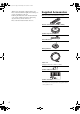
DTR-6.8_En.book Page 5 Wednesday, June 20, 2007 11:51 PM Table of Contents Introduction Important Safety Instructions ....................2 Precautions ..................................................3 Supplied Accessories..................................4 Features ........................................................6 Front & Rear Panels.....................................7 Front Panel..................................................... 7 Display....................................................
DTR-6.8_En.book Page 6 Wednesday, June 20, 2007 4:16 PM Features Amplification • 100 watts minimum continuous power per channel, 8 ohm loads, 2 channels driven from 20 Hz to 20 kHz with a maximum total harmonic distortion of 0.08 % (FTC rating) • WRAT-Wide Range Amplifier Technology (5 Hz-100 kHz bandwidth) • Optimum Gain Volume Circuitry *2. Manufactured under license from Dolby Laboratories. “Dolby”, “Pro Logic” and the double-D symbol are trademarks of Dolby Laboratories. *3.
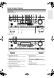
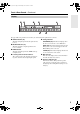
DTR-6.8_En.book Page 7 Wednesday, June 20, 2007 4:16 PM Front & Rear Panels Front Panel North American model 1 2 3 4 bq br bs 5 6 7 8 9 bk bl bm bn bo bt ck cl bp cm Australian model 2 cn 3 The page numbers in parentheses show where you can find the main explanation for each item. 1 Standby/On button (42) 5 Stereo button (77) This button is used to set the AV receiver to Standby This button is used to select the Stereo listening or On. mode.
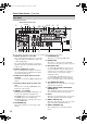
DTR-6.8_En.book Page 8 Wednesday, June 20, 2007 4:16 PM Front & Rear Panels—Continued 9 Memory button (76) This button is used when storing or deleting radio presets. bk Tuning Mode button (60) This button is used to select the Auto or Manual tuning mode. bl Display button (58) This button is used to display various information about the currently selected input source. bm Setup button This button is used to access the onscreen setup menus that appear on the connected TV.
DTR-6.8_En.book Page 9 Wednesday, June 20, 2007 4:16 PM Front & Rear Panels—Continued Display 1 2 3 4 6 5 7 The page numbers in parentheses show where you can find the main explanation for each item. 1 SLEEP indicator (59) This indicator lights up when the Sleep function has been set. 2 MUTING indicator (59) This indicator flashes or lights up while the AV receiver is muted. 3 HDMI indicator This indicator lights up when the HDMI audio signal input is used.
DTR-6.8_En.book Page 10 Wednesday, June 20, 2007 4:16 PM Front & Rear Panels—Continued Rear Panel North American model (North American model only) 1 2 34 5 6 bq brbsbt ck cl cm cn co 78 9 bkbl bm bn cp cq bo bp cr cs The page numbers in parentheses show where you can find the main explanation for each item. 1 DIGITAL OPTICAL IN 1, 2 and OUT 7 FM ANTENNA (23) These optical digital audio inputs are for connecting This jack is for connecting an FM antenna.
DTR-6.8_En.book Page 11 Wednesday, June 20, 2007 4:16 PM Front & Rear Panels—Continued bp AC INLET The supplied power cord is connected here. The other end of the power cord should be connected to a suitable wall outlet. bq PHONO IN This audio input is for connecting a turntable. br REMOTE CONTROL This (Remote Interactive) jack can be connected to an jack on another -capable Integra/Onkyo component. The AV receiver’s remote controller can then be used to control that component.
DTR-6.8_En.book Page 12 Wednesday, June 20, 2007 4:16 PM Remote Controller Installing the Batteries 1 To open the battery compartment, press the small hollow and slide off the cover. Aiming the Remote Controller To use the remote controller, point it at the AV receiver’s remote control sensor, as shown below. Remote control sensor AV receiver Standby indicator 2 3 Insert the three supplied batteries (AA/R6) in accordance with the polarity diagram inside the battery compartment.
DTR-6.8_En.book Page 13 Wednesday, June 20, 2007 4:16 PM Remote Controller—Continued About the Remote Controller Modes As well as the AV receiver, you can also use the remote controller to control your other AV components. The remote controller has a specific operating mode for use with each type of component. Modes are selected by using the Remote Mode buttons. Receiver/Tape Mode Receiver/Tape mode is used to control the AV receiver.
DTR-6.8_En.book Page 14 Wednesday, June 20, 2007 4:16 PM Remote Controller—Continued For detailed information, see the pages in parentheses. ck L Night button (86) Turns the Late Night function on or off. 1 Standby button (42) Sets the AV receiver to Standby. 2 On button (42) Turns on the AV receiver. 3 Input Selector buttons (57) Used to select the input source. 4 Macro buttons (120) Used with the Macro function. 5 Dimmer button (59) Adjusts the display brightness.
DTR-6.8_En.book Page 15 Wednesday, June 20, 2007 4:16 PM Remote Controller—Continued 1 Standby button DVD Mode Sets the DVD player to Standby. To set the remote controller to DVD mode, press the [DVD] Remote Mode button. 2 On button Turns on the DVD player. 3 Number buttons Used to enter title, chapter, and track numbers, and times for locating specific points. 4 Top Menu button 1 2 Selects a DVD’s top menu. 5 Arrow [ ]/[ ]/[ ]/[ ] and Enter buttons Used to navigate menus and select items.
DTR-6.8_En.book Page 16 Wednesday, June 20, 2007 4:16 PM Remote Controller—Continued 1 Standby button CD/MD/CDR Modes Sets the component to Standby. To control an Integra/Onkyo CD player, MD recorder, or CD recorder, or a CD or MD player/recorder made by another manufacturer, press the [CD] Remote Mode button to select the CD/MD/CDR remote controller mode.
DTR-6.8_En.book Page 17 Wednesday, June 20, 2007 4:16 PM Remote Controller—Continued 1 Standby button Dock Mode Turns off the iPod. Dock mode is for controlling an Apple iPod in an Onkyo RI Dock. When Using an RI Dock: • Connect the RI Dock to the TAPE IN or GAME/TV IN L/R jacks. • Set the RI Dock’s RI MODE switch to HDD or HDD/DOCK. • Set the AV receiver’s Input Display to DOCK (see page 48). • When operating a DS-A1 RI Dock, enter the appropriate remote control code for the first time (see page 116).
DTR-6.8_En.book Page 18 Wednesday, June 20, 2007 4:16 PM About Home Theater Enjoying Home Theater Thanks to the AV receiver’s superb capabilities, you can enjoy surround sound with a real sense of movement in your own home—just like being in a movie theater or concert hall. With DVDs you can enjoy DTS and Dolby Digital. With analog and digital TV you can enjoy Dolby Pro Logic IIx or Onkyo’s own DSP surround listening modes. You can also enjoy THX Surround EX (THX-certified THX speaker system recommended).
DTR-6.8_En.book Page 19 Wednesday, June 20, 2007 4:16 PM Connecting the AV Receiver AV Connection Color Coding About AV Connections • Before making any AV connections, read the manuals supplied with your other AV components. • Don’t connect the power cord until you’ve completed and double-checked all AV connections. Optical Digital Jacks The AV receiver’s optical digital jacks have shutter-type covers that open when an optical plug is inserted and close when it’s removed. Push plugs in all the way.
DTR-6.8_En.book Page 20 Wednesday, June 20, 2007 4:16 PM Connecting the AV Receiver—Continued Connecting a Powered Subwoofer Connecting Your Speakers Speaker Configuration For the best surround sound experience, you should connect seven speakers and a powered subwoofer. The following table indicates the channels you should use depending on the number of speakers that you have.
DTR-6.8_En.book Page 21 Wednesday, June 20, 2007 4:16 PM Connecting the AV Receiver—Continued Speaker Connection Precautions Read the following before connecting your speakers: • North American models: Only connect speakers with an impedance of 6 ohms or higher. If you use speakers with a lower impedance, and use the amplifier at high volume levels for a long period of time, the built-in protection circuit may be activated.
DTR-6.8_En.book Page 22 Wednesday, June 20, 2007 4:16 PM Connecting the AV Receiver—Continued Bi-amping the Front Speakers The FRONT SPEAKERS L/R and SURR BACK SPEAKERS L/R terminal posts can be used with front speakers and surround back speakers respectively, or biamped to provide separate tweeter and woofer feeds for a pair of front speakers that support bi-amping, providing improved bass and treble performance. • When bi-amping is used, the AV receiver is able to drive up to 5.
DTR-6.8_En.book Page 23 Wednesday, June 20, 2007 4:16 PM Connecting the AV Receiver—Continued Connecting Antenna This section explains how to connect the supplied indoor FM antenna and AM loop antenna, and how to connect commercially available outdoor FM and AM antennas. The AV receiver won’t pick up any radio signals without any antenna connected, so you must connect the antenna to use the tuner.
DTR-6.8_En.book Page 24 Wednesday, June 20, 2007 4:16 PM Connecting the AV Receiver—Continued Connecting an Outdoor FM Antenna Connecting an Outdoor AM Antenna If you cannot achieve good reception with the supplied indoor FM antenna, try a commercially available outdoor FM antenna instead. If good reception cannot be achieved using the supplied AM loop antenna, an outdoor AM antenna can be used in addition to the loop antenna, as shown.
DTR-6.8_En.book Page 25 Wednesday, June 20, 2007 4:16 PM Connecting the AV Receiver—Continued Connecting Both Audio & Video By connecting both the audio and video outputs of your DVD player and other AV components to the AV receiver, you can select both the audio and video simultaneously simply by selecting the appropriate input source on the AV receiver. : Signal Flow Video Video Audio Audio TV, projector, etc. DVD player, etc.
DTR-6.8_En.book Page 26 Wednesday, June 20, 2007 4:16 PM Connecting the AV Receiver—Continued ■ HDMI Monitor Setting Set to No With the HDMI Monitor setting set to No (see page 45), video input signals flow through the AV receiver as shown, with composite video and S-Video sources being upconverted for the component video output. Use this setting if you connect the AV receiver’s COMPONENT VIDEO OUT to your TV. Composite video is upconverted to S-Video and S-Video is downconverted to composite video.
DTR-6.8_En.book Page 27 Wednesday, June 20, 2007 4:16 PM Connecting the AV Receiver—Continued Connecting a TV or Projector Step 1: Video Connection Choose a video connection that matches your TV ( A , B , or C ), and then make the connection. Step 2: Audio Connection Choose an audio connection that matches your TV ( a , b , or c ), and then make the connection. • With connection a , you can listen to and record audio from your TV and listen in Zone 2.
DTR-6.8_En.book Page 28 Wednesday, June 20, 2007 4:16 PM Connecting the AV Receiver—Continued Connecting a DVD Player Step 1: Video Connection Choose a video connection that matches your DVD player ( A , B , or C ), and then make the connection. You must connect the AV receiver to your TV via the same type of connection. Step 2: Audio Connection Choose an audio connection that matches your DVD player ( a , b , or c ), and then make the connection.
DTR-6.8_En.book Page 29 Wednesday, June 20, 2007 4:16 PM Connecting the AV Receiver—Continued Hooking Up the Multichannel DVD Input If your DVD player supports multichannel audio formats such as DVD-Audio or SACD, and it has a multichannel analog audio output, you can connect it to the AV receiver’s multichannel DVD input. Use a multichannel analog audio cable, or several normal audio cables, to connect the AV receiver’s DVD FRONT L/R, CENTER, SURR L/R, SURR BACK L/R, and SUBWOOFER jacks to the 7.
DTR-6.8_En.book Page 30 Wednesday, June 20, 2007 4:16 PM Connecting the AV Receiver—Continued Connecting a VCR or DVD Recorder for Playback Hint! With this hookup, you can use your VCR’s tuner to listen to your favorite TV programs via the AV receiver, useful if your TV has no audio outputs. Step 1: Video Connection Choose a video connection that matches your VCR or DVD recorder ( A , B , or C ), and then make the connection. You must connect the AV receiver to your TV via the same type of connection.
DTR-6.8_En.book Page 31 Wednesday, June 20, 2007 4:16 PM Connecting the AV Receiver—Continued Connecting a VCR or DVD Recorder for Recording Step 1: Video Connection Choose a video connection that matches your VCR or DVD recorder ( A or B ), and then make the connection. The video source to be recorded must be connected to the AV receiver via the same type of connection. Step 2: Audio Connection Make the connection a .
DTR-6.8_En.book Page 32 Wednesday, June 20, 2007 4:16 PM Connecting the AV Receiver—Continued Connecting a Satellite, Cable, Set-top box, or Other Video Source Hint! With this hookup, you can use your satellite or cable receiver to listen to your favorite TV programs via the AV receiver, useful if your TV has no audio outputs. Step 1: Video Connection Choose a video connection that matches the video source ( A , B , or C ), and then make the connection.
DTR-6.8_En.book Page 33 Wednesday, June 20, 2007 4:16 PM Connecting the AV Receiver—Continued Connecting a Game Console Step 1: Video Connection Choose a video connection that matches the game console ( A , B , or C ), and then make the connection. If you use connection A , you must connect the AV receiver to your TV with the same type of connection. Step 2: Audio Connection Choose an audio connection that matches the game console ( a or b ), and then make the connection.
DTR-6.8_En.book Page 34 Wednesday, June 20, 2007 4:16 PM Connecting the AV Receiver—Continued Connecting a Camcorder or Other Device Step 1: Video Connection Choose a video connection that matches the camcorder ( A or B ), and then make the connection. Step 2: Audio Connection Choose an audio connection that matches the camcorder ( a or b ), and then make the connection.
DTR-6.8_En.book Page 35 Wednesday, June 20, 2007 4:16 PM Connecting the AV Receiver—Continued Connecting Components with HDMI About HDMI Designed to meet the demands of digital TV, HDMI (High Definition Multimedia Interface) is a new digital interface standard for connecting TVs, projectors, DVD players, set-top boxes, and other video components. Until now, several separate video and audio cables have been required to connect AV components.
DTR-6.8_En.book Page 36 Wednesday, June 20, 2007 4:16 PM Connecting the AV Receiver—Continued Making HDMI Connections Step 1: Use HDMI cables to connect the AV receiver’s HDMI jacks to your HDMI-compatible DVD player, TV, projector, and so on. Step 2: Assign each HDMI IN to an input selector in the HDMI Input Setup (see page 46). ■ Video Signals Digital video signals received by the HDMI IN jacks are normally output by the HDMI OUT for display on your TV.
DTR-6.8_En.book Page 37 Wednesday, June 20, 2007 4:16 PM Connecting the AV Receiver—Continued Connecting a CD Player or Turntable ■ CD Player or Turntable (MM) with Built-in Phono Preamp Step 1: Choose a connection that matches your CD player ( a , b , or c ). Use connection a for a turntable with a built-in phono preamp.
DTR-6.8_En.book Page 38 Wednesday, June 20, 2007 4:16 PM Connecting the AV Receiver—Continued Connecting a Cassette, CDR, MiniDisc, or DAT Recorder Step 1: Choose a connection that matches the recorder ( a , b , c or d ), and then make the connection. b COAXIAL IN 3 (CBL/SAT) a IN L c R OPTICAL IN 1 (GAME/TV) TAPE d OPTICAL a L R TAPE Connect one or the other L COAXIAL OUT OPTICAL OUT R AUDIO IN OPTICAL IN L R AUDIO OUT Cassette, CDR, MD, etc.
DTR-6.8_En.book Page 39 Wednesday, June 20, 2007 4:16 PM Connecting the AV Receiver—Continued Connecting a Power Amplifier If you want to use a more powerful power amplifier and use the AV receiver as a preamp, connect it to the PRE OUT jacks, and connect all speakers and the subwoofer to the power amplifier. If you have a powered subwoofer, connect it to this AV receiver’s PRE OUT SUBWOOFER jack. 1. Subwoofer 2. Front left speaker 3. Center speaker 4. Front right speaker 5. Surround left speaker 6.
DTR-6.8_En.book Page 40 Wednesday, June 20, 2007 11:52 PM Connecting the AV Receiver—Continued Connecting an RI Dock ■ iPod with video Connect your RI Dock’s analog audio output jacks and Video output jack to the AV receiver’s GAME/TV IN L/R jacks and GAME/TV IN V jack. (Onkyo DS-A2 hookup shown below.) VIDEO OUT ■ iPod without video Connect your RI Dock’s analog audio output jacks to the AV receiver’s TAPE IN L/R jacks. (Onkyo DSA2 hookup shown below.
DTR-6.8_En.book Page 41 Wednesday, June 20, 2007 11:52 PM Connecting the AV Receiver—Continued Connecting Components IN L Step 1: Make sure that each Integra/Onkyo component is connected to the AV receiver with an analog audio cable (connection a in the hookup examples) (see pages 27 to 40). Step 2: Make the R CD FRONT REMOTE CONTROL L R connection. Step 3: If you’re using an MD, CDR, or RI Dock, change the input display (see page 48). DVD e.g.
DTR-6.8_En.book Page 42 Wednesday, June 20, 2007 4:16 PM Turning On the AV Receiver Standby/On Standby Standby indicator On Receiver Turning On and Standby 1 Remote controller AV receiver or Receiver On Press the [Standby/On] button. Alternatively, press the remote controller’s [Receiver] button, followed by the [On] button. The AV receiver comes on, the display lights up, and the Standby indicator goes off.
DTR-6.8_En.book Page 43 Wednesday, June 20, 2007 11:52 PM First Time Setup This section explains the settings that you need to make before using the AV receiver for the very first time. ■ Menus for First Time Setup Submenus 1. Input/Output Assign 1. 2. 3. 4. Monitor Out HDMI Input Component Video Input Digital Input p. 45 p. 49 2. Speaker Setup 1 2 1. 2. 3. 4. 5. 6. 2 1 Speaker Settings Speaker Config Speaker Distance Level Calibration Equalizer Settings THX Audio Setup p.
DTR-6.8_En.book Page 44 Wednesday, June 20, 2007 4:16 PM First Time Setup—Continued Speaker Settings 4 Use the Up and Down [ ]/[ ] buttons to select “Speaker Impedance,” and then use the Left and Right [ ]/[ ] buttons to select: 4 ohms: Select if the impedance of any speaker is 4 ohms or more but less than 6. 6 ohms: Select if the impedances of all speakers are between 6 and 16 ohms.
DTR-6.8_En.book Page 45 Wednesday, June 20, 2007 4:16 PM First Time Setup—Continued 1 2, 3 1 Press the [Receiver] button followed by the [Setup] button. The main menu appears onscreen. 2 Use the Up and Down [ ]/[ ] buttons to select “1. Input/Output Assign,” and then press [Enter]. The Input/Output Assign menu appears. 2-4 1. Input/Output Assign 1, 5 1. 2. 3. 4.
DTR-6.8_En.book Page 46 Wednesday, June 20, 2007 4:16 PM First Time Setup—Continued 3 Video Input Setup HDMI Input Setup If you connect a video component to HDMI IN, you must assign that input to an input selector. For example, if you connect your DVD player to HDMI IN 1, you must assign HDMI IN 1 to the DVD input selector.
DTR-6.8_En.book Page 47 Wednesday, June 20, 2007 4:16 PM First Time Setup—Continued Component Video Setup If you connect to a COMPONENT VIDEO IN, you must assign it to an input selector. For example, if you connect your DVD player to COMPONENT IN 3, you should assign it to the DVD input selector. If you want to output composite and S-Video sources from the COMPONENT VIDEO OUT, select “---,” as explained below.
DTR-6.8_En.book Page 48 Wednesday, June 20, 2007 4:16 PM First Time Setup—Continued Changing the Input Display If you connect an -capable Onkyo MiniDisc recorder, CD recorder, or RI Dock to the TAPE IN/OUT or GAME/TV IN jacks, for to work properly, you must change this setting. This setting can only be changed on the AV receiver. 1, 2 1, 2 iPod photo: If you’re using an iPod photo with the RI Dock, connect the RI Dock to the GAME/TV IN jacks.
DTR-6.8_En.book Page 49 Wednesday, June 20, 2007 4:16 PM First Time Setup—Continued Digital Input Setup 4 Use the Up and Down [ ]/[ ] buttons to select an input selector, and use the Left and Right [ ]/[ ] buttons to select COAX 1, COAX 2, COAX 3, OPT 1, OPT 2, or - - - (analog). • An input selector that has been assigned to IN 1, IN 2 or IN 3 in the “HDMI Input Setup” (see page 46) can be set to HDMI here. • There are no assignments for TUNER.
DTR-6.8_En.book Page 50 Wednesday, June 20, 2007 4:16 PM First Time Setup—Continued TV Format Setup (not North American model) 5 You must specify the TV system used in your area. 1 2 Press the [Receiver] button followed by the [Setup] button. The main menu appears onscreen. Use the Up and Down [ ]/[ ] buttons to select “6. Miscellaneous,” and then press [Enter]. The Miscellaneous menu appears. 6. Miscellaneous 1. 2. 3. 4. 5.
DTR-6.8_En.book Page 51 Wednesday, June 20, 2007 4:16 PM First Time Setup—Continued AM Frequency Step Setup (Australian model) You must specify the AM frequency step used in your area. Note that when this setting is changed, all radio presets are deleted. 1 Press the [Receiver] button, followed by the [Setup] button. The main menu appears onscreen. 2 Use the Up and Down [ ]/[ ] buttons to select “7. Hardware Setup,” and then press [Enter]. The Hardware Setup menu appears.
DTR-6.8_En.book Page 52 Wednesday, June 20, 2007 4:16 PM First Time Setup—Continued Using Audyssey MultEQ XT Automatic Speaker Setup (Audyssey MultEQ XT) With the supplied speaker setup microphone, the Audyssey MultEQ XT function can measure the number of speakers connected, their sizes, crossover frequencies, and the distance from each speaker to the listening position and calculate the optimal speaker settings for your listening environment automatically.
DTR-6.8_En.book Page 53 Wednesday, June 20, 2007 4:16 PM First Time Setup—Continued 1 2 Turn on the AV receiver and the connected TV. On the TV, select the input to which the AV receiver is connected. 4 Auto Speaker Setup AUDYSSEY - - - - - SP Detect Result - - - - FL SL SBL C Put the speaker setup microphone at measurement point 1 (page 52), and connect it to the Setup Mic jack. Auto Speaker Setup The speaker detect results appear.
DTR-6.8_En.book Page 54 Wednesday, June 20, 2007 4:16 PM First Time Setup—Continued 7 After the 3rd to the 7th measurement, the following screen appears. Auto Speaker Setup Use the Up and Down [ ]/[ ] buttons to select an option, and then press [Enter]. The options are: Save: Save the calculated settings and exit the automatic speaker setup. Review SP Config: Review the speaker configuration settings (see “Reviewing the Results” on page 56).
DTR-6.8_En.book Page 55 Wednesday, June 20, 2007 4:16 PM First Time Setup—Continued Error Messages Auto Speaker Setup While the automatic speaker setup is in progress, one of the following error messages may appear: - - - - - Speaker Detect Error - - - - - ❏ Ambient noise is too high. FL SL SBL C Auto Speaker Setup AUDYSSEY : : : : Yes --No Yes FR SR SBR SW : : : : AUDYSSEY Yes Yes Yes --- Retry Cancel Ambient noise is too high.
DTR-6.8_En.book Page 56 Wednesday, June 20, 2007 4:16 PM First Time Setup—Continued Reviewing the Results Changing the Speaker Settings Manually Use the Up and Down [ ]/[ ] buttons to select the settings that you want to review, and then press [Enter]. Auto Speaker Setup AUDYSSEY Save Review SP Config Review SP Distance Review SP Level Cancel The options are: Review SP Config: Review the speaker configuration settings.
DTR-6.8_En.book Page 57 Wednesday, June 20, 2007 11:53 PM Basic Operations Selecting the Input Source This section explains how to select the input source (i.e., the AV component that you want to listen to or watch). Multi CH 3 Multi CH 1 1 3 1 1 Remote controller AV receiver Use the AV receiver’s input selector buttons to select the input source. Receiver To select the input source with the remote controller, press the [Receiver] button, and then use the Input Selector buttons.
DTR-6.8_En.book Page 58 Wednesday, June 20, 2007 4:16 PM Basic Operations—Continued Using the Multichannel DVD Input The multichannel DVD input is for connecting a component with a 7.1-channel analog audio output, such as a DVD-Audio or SACD-capable DVD player, or an MPEG decoder. See page 29 for hookup information. Press the [Receiver] button, followed by the [Multi CH] button. The MULTI CH indicator appears on the display.
DTR-6.8_En.book Page 59 Wednesday, June 20, 2007 4:16 PM Basic Operations—Continued Using the Sleep Timer Press [Receiver] first Sleep Dimmer Muting Setting the Display Brightness You can adjust the brightness of the display. Press the [Receiver] button, and then press the [Dimmer] button repeatedly to select: Normal, Dim, or Dimmer. Alternatively, you can use the AV receiver’s [Dimmer] button. With the sleep timer, you can set the AV receiver to turn off automatically after a specified period.
DTR-6.8_En.book Page 60 Wednesday, June 20, 2007 4:16 PM Listening to the Radio ■ Manual Tuning Mode Using the Tuner With the built-in tuner you can enjoy AM and FM radio stations. You can store your favorite stations as presets for quick selection. 1 Press the [Tuning Mode] button so that the AUTO indicator disappears from the display. 2 Press and hold the Tuning Up or Down [ ]/[ ] buttons. The frequency stops changing when you release the button.
DTR-6.8_En.book Page 61 Wednesday, June 20, 2007 4:16 PM Listening to the Radio—Continued Listening to XM Satellite Radio® (North American Models Only) Important XM Radio Information XM Satellite Radio offers an extraordinary variety of commercial-free music, plus the best in sports, news, talk and entertainment. XM is broadcast in superior digital audio from coast to coast. From rock to reggae, from classical to hip hop, XM has something for every music fan.
DTR-6.8_En.book Page 62 Wednesday, June 20, 2007 4:16 PM Listening to the Radio—Continued 4 Use the Left and Right [ ]/[ ] buttons to select “XM.” Pressing the Left and Right [ ]/[ ] buttons cycles through the following SAT options: None → XM → SIRIUS → XM/SIRIUS None: Select if you’re not using Satellite Radio. XM: Select to use XM Satellite Radio. SIRIUS: Select to use SIRIUS Satellite Radio. XM/SIRIUS: Select to use XM Satellite Radio and SIRIUS Satellite Radio. 5 Press the [Setup] button.
DTR-6.8_En.book Page 63 Wednesday, June 20, 2007 11:53 PM Listening to the Radio—Continued Notes: • RADIO ID cannot be selected in Category Search mode. You must select Channel Search mode (see below). • The following letters are not used in XM Satellite Radio IDs: I, O, S, F. • XM Satellite Radio will transmit a special signal to your AV receiver to activate the full channel lineup.
DTR-6.8_En.book Page 64 Wednesday, June 20, 2007 4:16 PM Listening to the Radio—Continued Selecting the Previous Channel: Enter Tuning Preset / 1 AV receiver To listen to the previously selected XM channel, press the [Return] button. Remote controller Return Display Tuning Mode Memory Displaying XM Radio Information 1 CH + / – Display AV receiver Press the [Display] button repeatedly to cycle through the available information.
DTR-6.8_En.book Page 65 Wednesday, June 20, 2007 4:16 PM Listening to the Radio—Continued Tuning / Enter 3 Use the Up and Down [ ]/[ ] buttons to select “4. Satellite Radio,” and then press [Enter]. The Satellite Radio menu appears. 4-4. Satellite Radio XM Antenna Aiming Setup Satellite Terrestrial Positioning the XM Mini-Tuner System You can check the signal strength of the XM radio signal and adjust the position of the XM Mini-Tuner System accordingly.
DTR-6.8_En.book Page 66 Wednesday, June 20, 2007 4:16 PM Listening to the Radio—Continued XM Radio Messages The following messages may appear while using XM radio. ❑ CHECK ANTENNA The XM antenna is not properly connected to the Mini-Tuner Dock. Check the connection. Check the antenna cable for damage. ❑ UPDATING XM is updating your Mini-Tuner with the latest encryption code. Simply wait a few seconds until the update is done.
DTR-6.8_En.book Page 67 Wednesday, June 20, 2007 4:16 PM Listening to the Radio—Continued Listening to SIRIUS Satellite Radio® (North American Models Only) Important SIRIUS Satellite Radio Information SIRIUS is available in the US for subscribers with addresses in the continental US and is available in Canada for subscribers with a Canadian address. To Get SIRIUS Satellite Radio a subscription and compatible tuner and antenna are required and sold separately. Visit sirius.
DTR-6.8_En.book Page 68 Wednesday, June 20, 2007 4:16 PM Listening to the Radio—Continued Positioning the Antenna For a consistent satellite signal, the antenna must be positioned correctly. Use the following map to determine which area you are in and position the antenna accordingly. 2 Use the Up and Down [ ]/[ ] buttons to select “7. Hardware Setup,” and then press [Enter]. The Hardware Setup menu appears. 7. Hardware Setup SKY 1. 2. 3. 4. 5. 6.
DTR-6.8_En.book Page 69 Wednesday, June 20, 2007 4:16 PM Listening to the Radio—Continued Selecting SIRIUS Satellite Radio 1 Press the [Tuner] input selector button repeatedly to select “SIRIUS.” If “CHECK SR TUNER” appears on the display, make sure the SiriusConnect receiver is connected properly. If “ANTENNA ERROR” appears, make sure the antenna is connected properly.
DTR-6.8_En.book Page 70 Wednesday, June 20, 2007 4:16 PM Listening to the Radio—Continued ■ Category Search Mode 1 Press the [Receiver] button, followed by the [Enter] button to select “Category Search” mode. Enter Tuning Preset / Return Display Tuning Mode Memory 2 Use the Left and Right [ ]/[ ] buttons to select a category, and use the Up and Down [ ]/[ ] buttons to select a channel in that category.
DTR-6.8_En.book Page 71 Wednesday, June 20, 2007 4:16 PM Listening to the Radio—Continued Selecting the Previous Channel: 1 AV receiver To listen to the previously selected SIRIUS Satellite Radio channel, press the [Return] button. Parental Lock You can lock out channels that you do not want to receive. 1 Remote controller Press the [Receiver] button followed by the [Setup] button. The main menu appears onscreen. Remote controller 2 Use the Up and Down [ ]/[ ] buttons to select “4.
DTR-6.8_En.book Page 72 Wednesday, June 20, 2007 4:16 PM Listening to the Radio—Continued 4 Press the [D. TUN] button, and then use the number buttons to enter the PIN number. 7 4-5. SIRIUS Parental Lock Or Parental Lock Channel 50 ch Use the Left and Right [ ]/[ ] buttons to select the number, and then press [Enter]. Repeat this for each digit in the PIN number. If you enter the wrong PIN number, “Wrong Code!” appears on the display. You’ll be returned to step 3, and will need to start again.
DTR-6.8_En.book Page 73 Wednesday, June 20, 2007 4:16 PM Listening to the Radio—Continued Changing the PIN Number 1 Remote controller 2 4 Press the [Receiver] button followed by the [Setup] button. The main menu appears onscreen. Press the [D. TUN] button, and then use the number buttons to enter the PIN number. If you enter the wrong PIN number, “Wrong Code!” appears on the display. You’ll be returned to step 3, and will need to start again. The SIRIUS Parental Lock menu appears.
DTR-6.8_En.book Page 74 Wednesday, June 20, 2007 4:16 PM Listening to the Radio—Continued 7 Enter the new PIN number again. If you enter the wrong PIN number, “Wrong Code!” appears on the display. You’ll be returned to step 4, and will need to start again. 8 Press the [Setup] button. The setup menu closes. Note: • If the category, artist/composer, or song title is not available, “- - -” will be displayed instead. • This procedure can also be performed on the AV receiver by using its [Display] button.
DTR-6.8_En.book Page 75 Wednesday, June 20, 2007 11:54 PM Listening to the Radio—Continued 3 Use the Up and Down [ ]/[ ] buttons to select “4. Satellite Radio,” and then press [Enter]. The Satellite Radio menu appears. SIRIUS Satellite Radio Messages The following messages may appear while using SIRIUS Satellite Radio. ❑ ACQUIRING 4-4. Satellite Radio SIRIUS Antenna Aiming Satellite SIRIUS ID Terrestrial ------------ The SiriusConnect receiver is acquiring the signal or no signal is present.
DTR-6.8_En.book Page 76 Wednesday, June 20, 2007 4:16 PM Listening to the Radio—Continued Presetting AM, FM, XM, and SIRIUS Stations 2, 4 Selecting Presets Preset 3 You can store a combination of up to 40 of your favorite AM, FM, XM, and SIRIUS radio stations as presets. 1 Tune into the AM, FM, XM, and SIRIUS station that you want to store as a preset. 2 Press the [Memory] button. The preset number flashes.
DTR-6.8_En.book Page 77 Wednesday, June 20, 2007 4:16 PM Using the Listening Modes Selecting Listening Modes Selecting with the Remote Controller See “About the Listening Modes” on page 82 for detailed information about the listening modes. • The Dolby Digital and DTS listening modes can only be selected if your DVD player is connected to the AV receiver with a digital audio connection (coaxial or optical). • Listening mode availability depends on the format of the current input signal.
DTR-6.8_En.book Page 78 Wednesday, June 20, 2007 4:16 PM Using the Listening Modes—Continued Listening Modes Available for Each Source Format Analog and PCM Sources ✔: Can be selected. PCM Source format 32–96 kHz Media Button [Direct] Listening Mode CD, TV, radio, ✔ ✔ Direct [Stereo] Stereo [Surround] ✔ ✔ Multichannel PCM except */2 DVD ✔ Neural THX 5.1 Neural THX 7.
DTR-6.8_En.book Page 79 Wednesday, June 20, 2007 4:16 PM Using the Listening Modes—Continued DSD, Dolby Digital, and Dolby Digital Plus Sources ✔: Can be selected. DSD*1 Source format 3/2 Media Button [Direct] Direct Stereo 2ch ✔ ✔ Dolby Digital Plus Multichannel except */2 SACD Listening Mode [Stereo] Dolby D Multichannel */2 Multichannel 2ch 1/0, 1+1 except */2 DVD, DTV, etc.
DTR-6.8_En.book Page 80 Wednesday, June 20, 2007 4:16 PM Using the Listening Modes—Continued TrueHD and DTS Sources ✔: Can be selected. TrueHD*1 Source format except */ 2 Media Button [Direct] Direct Stereo */2 ✔ ✔ ✔ ✔ 1/0 DTS-ES Discrete/ Matrix ✔ ✔ ✔ ✔ Multichannel 2ch 1/0, 1+1 except */ 2 */2 Blu-ray, HD DVD Listening Mode [Stereo] DTS, DTS96/24 Multichannel ✔ ✔ 2ch DVD, CD, etc.
DTR-6.8_En.book Page 81 Wednesday, June 20, 2007 4:16 PM Using the Listening Modes—Continued DTS-HD Sources ✔: Can be selected.
DTR-6.8_En.book Page 82 Wednesday, June 20, 2007 4:16 PM Using the Listening Modes—Continued About the Listening Modes The AV receiver’s listening modes can transform your listening room into a movie theater or concert hall, with high fidelity and stunning surround sound. Direct In this mode, audio from the input source is output directly with minimal processing, providing high-fidelity reproduction. All of the source’s audio channels are output as they are.
DTR-6.8_En.book Page 83 Wednesday, June 20, 2007 4:16 PM Using the Listening Modes—Continued DTS-ES Matrix DSD This mode is for use with DTS-ES Matrix soundtracks, which use a matrix-encoded back-channel for 6.1/7.1channel playback. Use it with DVDs that bear the DTSES logo, especially those with a DTS-ES Matrix soundtrack. DSD stands for Direct Stream Digital and is the format used to store digital audio on Super Audio CDs (SACD). This mode can be used with SACDs that feature multichannel audio.
DTR-6.8_En.book Page 84 Wednesday, June 20, 2007 4:16 PM Using the Listening Modes—Continued Onkyo Original DSP Modes Mono Movie This mode is suitable for old movies and other mono sources. The center speaker outputs the sound as it is, while reverb is applied to the sound output by the other speakers, giving presence to even mono material.
DTR-6.8_En.book Page 85 Wednesday, June 20, 2007 4:16 PM Recording This section explains how to record the selected input source to a component with recording capability, and how to record audio and video from different sources. Notes: • The surround sound and DSP listening modes cannot be recorded. • Copy-protected DVDs cannot be recorded. • You cannot record from the DVD analog multichannel input. • Various restrictions apply to digital recording.
DTR-6.8_En.
DTR-6.8_En.book Page 87 Wednesday, June 20, 2007 11:54 PM Advanced Setup About the Onscreen Setup Menus The onscreen setup menus are displayed on the connected TV and provide a convenient way to change the AV receiver’s settings. Submenus p. 45 p. 49 1. 2. 3. 4. p. 88 p. 94 p. 44 Submenus 1. Input/Output Assign 1. 2. 3. 4. 5. 6. 7. 8. 9. DVD VCR/DVR CBL/SAT GAME/TV AUX TAPE TUNER CD PHONO p. 103 6. Miscellaneous 2. Speaker Setup 1. 2. 3. 4. 5. 6. p. 98 5.
DTR-6.8_En.book Page 88 Wednesday, June 20, 2007 4:16 PM Advanced Setup—Continued Speaker Setup Some of the settings in this section are set automatically by the Automatic Speaker Setup function (see page 52). Here you can check the settings made by the Automatic Speaker Setup function, or set them manually, which is useful if you change one of the connected speakers after using the Automatic Speaker Setup function.
DTR-6.8_En.book Page 89 Wednesday, June 20, 2007 4:16 PM Advanced Setup—Continued 5 Use the Up and Down [ ]/[ ] buttons to select “Front,” and then use the Left and Right [ ]/ [ ] buttons to select a crossover frequency. Note: If the Subwoofer setting in step 4 is set to No, this setting is fixed at Full Band. 9 Use the Up and Down [ ]/[ ] buttons to select “Surr Back Ch,” and then use the Left and Right [ ]/[ ] buttons to select: 1ch: Select if one surround back speaker is connected.
DTR-6.8_En.book Page 90 Wednesday, June 20, 2007 4:16 PM Advanced Setup—Continued Double Bass This setting is not set automatically by the Automatic Speaker Setup function (see page 52). With the Double Bass function, you can boost bass output by feeding bass sounds from the front left and right channels to the subwoofer. This function can be set only if the Subwoofer setting in step 4 is set to Yes, and the Front setting in step 5 is set to Full Band.
DTR-6.8_En.book Page 91 Wednesday, June 20, 2007 4:16 PM Advanced Setup—Continued Speaker Distance Note: Speakers that you set to No or None on the Speaker Configuration page (page 88) cannot be selected. This setting is set automatically by the Automatic Speaker Setup function (see page 52). Here you can specify the distance from each speaker to the listening position so that the sound from each speaker arrives at the listener’s ears as the sound designer intended.
DTR-6.8_En.book Page 92 Wednesday, June 20, 2007 4:16 PM Advanced Setup—Continued Speaker Level Calibration 3 This setting is set automatically by the Automatic Speaker Setup function (see page 52). Here you can adjust the level of each speaker with the built-in test tone so that the volume of each speaker is the same at the listening position. Notes: • The speakers cannot be calibrated while the output of the AV receiver is muted.
DTR-6.8_En.book Page 93 Wednesday, June 20, 2007 4:16 PM Advanced Setup—Continued Equalizer Setting 4 Use the Left and Right [ ]/[ ] buttons to select: Off: Tone off, response flat. Audyssey: The tone for each speaker is set automatically by the Automatic Speaker Setup function. Be sure to select this setting after having performed the Automatic Speaker Setup. Manual: You can adjust the EQ of each speaker manually. If you select Manual, continue with this procedure.
DTR-6.8_En.book Page 94 Wednesday, June 20, 2007 4:16 PM Advanced Setup—Continued 7 Use the Up and Down [ ]/[ ] buttons to select “Channel,” and then use the Left and Right [ ]/ [ ] buttons to select another speaker. Repeat step 6 and 7 for each speaker. 2 2. Speaker Setup 1. 2. 3. 4. 5. 6. 3 8 Use the Up and Down [ ]/[ ] buttons to select “2. Speaker Setup,” and then press [Enter]. The Speaker Setup menu appears. Press the [Setup] button. The setup menu closes.
DTR-6.8_En.book Page 95 Wednesday, June 20, 2007 11:55 PM Advanced Setup—Continued Multichannel DVD Input Settings 5 Press the [Setup] button. The setup menu closes. Subwoofer Input Sensitivity Some DVD players output the LFE channel from their subwoofer output at 15 dB higher than normal. You can change the subwoofer sensitivity to match your DVD player. Note that this setting only affects signals connected to the SUBWOOFER input jack of the multichannel DVD input.
DTR-6.8_En.book Page 96 Wednesday, June 20, 2007 4:16 PM Advanced Setup—Continued Audio Adjust Functions Here you can set listening mode-related settings and functions. 1 5 When you’ve finished, press the [Setup] button. The setup menu closes. Press the [Receiver] button followed by the [Setup] button. The main menu appears onscreen. Note: This procedure can also be performed on the AV receiver by using its [Setup] button, arrow buttons, and [Enter] button.
DTR-6.8_En.book Page 97 Wednesday, June 20, 2007 4:16 PM Advanced Setup—Continued PLIIx/Neo:6 Music Mode Settings Dolby EX Input Signal Setting These settings provide for playing any 2-channel digital source such as Dolby Digital, or 2-channel analog/PCM source in the Dolby PLIIx Music listening mode. ■ Dolby EX This setting determines how Dolby EX encoded signals are handled. This setting is unavailable if no surround back speakers are connected.
DTR-6.8_En.book Page 98 Wednesday, June 20, 2007 4:16 PM Advanced Setup—Continued Assigning Listening Modes to Input Sources You can assign a default listening mode to each input source that will be selected automatically when you select each input source. For example, you can set the default listening mode to be used with Dolby Digital input signals. You can select other listening modes during playback, but the mode specified here will be resumed once the AV receiver has been set to Standby.
DTR-6.8_En.book Page 99 Wednesday, June 20, 2007 4:16 PM Advanced Setup—Continued 5 When you’ve finished, press the [Setup] button. The setup menu closes. 2 Use the Up and Down [ ]/[ ] buttons to select “4. Source Setup,” and then press [Enter]. The Source Setup menu appears. 4. Source Setup DVD 1. IntelliVolume 2. A/V Sync 3. Name Edit Note: This procedure can also be performed on the AV receiver by using its [Setup] button, arrow buttons, and [Enter] button.
DTR-6.8_En.book Page 100 Wednesday, June 20, 2007 4:16 PM Advanced Setup—Continued Correcting Sound and Picture Sync When using progressive scanning on your DVD player, you may find that the picture and sound are out of sync. With this setting, you can correct this by delaying the audio signals. You can set it from 0 to 250 milliseconds (msec) in 5 millisecond steps. 1 4 Use the Up and Down [ ]/[ ] buttons to select “2. A/V Sync,” and then press [Enter]. The A/V Sync menu appears. 4–2.
DTR-6.8_En.book Page 101 Wednesday, June 20, 2007 4:16 PM Advanced Setup—Continued Name Edit You can enter a custom name for each individual input selector and radio preset for easy identification. When selected, the custom name will appear on the display. 1 Select the input selector to which you want to give a custom name. To name a radio preset, use the [Tuner] button to select AM or FM, and then select the preset. 2 Press the [Receiver] Remote Mode button, followed by the [Setup] button.
DTR-6.8_En.book Page 102 Wednesday, June 20, 2007 4:16 PM Advanced Setup—Continued 8 When you’ve finished, use the arrow [ ]/[ ]/[ ]/[ ] buttons to display the following screen, select “OK,” and then press [Enter]. 4-3. Name Edit Name 123456789 “OK” 9 Press the [Setup] button. Setup closes. Notes: • To store a name, you must select “OK” and press [Enter] in step 8, otherwise it will not be saved. • You cannot enter a custom name for XM or SIRIUS radio presets.
DTR-6.8_En.book Page 103 Wednesday, June 20, 2007 4:16 PM Advanced Setup—Continued Muting Level Volume Setup/OSD Setup This setting determines how much the output is muted when the Muting function is used (see page 59). It can be set to – ∞ dB (fully muted) or from –50 dB to –10 dB in 10 dB steps. This section explains the items on the Miscellaneous menu. Volume Setup 1 Press the [Receiver] button followed by the [Setup] button. The main menu appears onscreen.
DTR-6.8_En.book Page 104 Wednesday, June 20, 2007 4:16 PM Advanced Setup—Continued OSD Setup 1 4 Press the [Receiver] button followed by the [Setup] button. The main menu appears onscreen. Use the Up and Down [ ]/[ ] buttons to select the settings, and use the Left and Right [ ]/ [ ] buttons to set them. These settings determine how the operation details are displayed.
DTR-6.8_En.book Page 105 Wednesday, June 20, 2007 4:16 PM Advanced Setup—Continued . Changing the AV Receiver’s ID HDMI Setup 1 Press the [Receiver] button followed by the [Setup] button. The main menu appears onscreen. 1 Press the [Receiver] button followed by the [Setup] button. The main menu appears onscreen. 2 Use the Up and Down [ ]/[ ] buttons to select “7. Hardware Setup,” and then press [Enter]. The Hardware Setup menu appears. 2 Use the Up and Down [ ]/[ ] buttons to select “7.
DTR-6.8_En.book Page 106 Wednesday, June 20, 2007 4:16 PM Advanced Setup—Continued HDMI Audio Out This preference determines whether audio received at the HDMI IN is output by the HDMI OUT. You may want to turn this preference on if your TV is connected to the HDMI OUT and you want to listen to the audio from a component that’s connected to an HDMI IN, through your TV’s speakers. Normally, this should be set to Off. Off: HDMI audio is not output (default). On: HDMI audio is output.
6_Advnced_En.fm Page 107 Wednesday, June 20, 2007 8:53 PM Advanced Setup—Continued Network Setup These settings are for use with home automation equipment and external controllers. Lock Setup 1 Press the [Receiver] button followed by the [Setup] button. The main menu appears onscreen. 2 Use the Up and Down [ ]/[ ] buttons to select “8. Lock Setup,” and then press [Enter]. The Lock Setup menu appears. 8.
6_Advnced_En.fm Page 108 Wednesday, June 20, 2007 8:53 PM Advanced Setup—Continued Digital Input Signal Formats The digital input signal formats are available only for the input sources that you have assigned a digital input jack; otherwise you will see “Analog” indicated on the screen (see page 49). Normally, the AV receiver detects the signal format automatically.
DTR-6.8_En.book Page 109 Wednesday, June 20, 2007 4:16 PM Zone 2 Using Only Speakers in Zone 2 Connecting Zone 2 With the Zone 2 function, you can enjoy one input source in the main room and a different source in another room. 1) Use another amp (receiver, integrated amp, or power amp) in Zone 2 and connect your Zone 2 speakers to it. 2) Connect your Zone 2 speakers to this AV receiver. Note: For speaker connections and related cautions, see page 21. With this connection method, you can use 5.
DTR-6.8_En.book Page 110 Wednesday, June 20, 2007 11:55 PM Zone 2—Continued 5 Setting the Powered Zone 2 To use Zone 2, you must make this setting. It enables the speakers connected to the ZONE 2 SPEAKERS terminals so that they produce sound when Zone 2 is used. 1 2 Press the [Receiver] button followed by the [Setup] button. The main menu appears onscreen. Use the Up and Down [ ]/[ ] buttons to select “7. Hardware Setup,” and then press [Enter]. The Hardware Setup menu appears. 7. Hardware Setup 1.
DTR-6.8_En.book Page 111 Wednesday, June 20, 2007 4:16 PM Zone 2—Continued . Setting the Zone 2 Out 5 If you’ve connected your Zone 2 speakers to a power amp with no volume control in Zone 2, as explained in “Using Another Amp in Zone 2” on page 109, you must set the Zone 2 Out setting to Variable. When set to Variable, the ZONE 2 OUT L/R jacks work like pre outs. 1 Press the [Receiver] button followed by the [Setup] button. The main menu appears onscreen.
DTR-6.8_En.book Page 112 Wednesday, June 20, 2007 4:16 PM Zone 2—Continued Using Zone 2 Controlling Zone 2 with the Remote Controller This section explains how to turn Zone 2 on and off, how to select an input source for Zone 2, and how to adjust the volume for Zone 2. On Controlling Zone 2 from the AV receiver Input Selector 1 2 Zone 2 1 To turn on Zone 2 and select an input source, press the [Zone 2] button repeatedly.
DTR-6.8_En.book Page 113 Wednesday, June 20, 2007 4:16 PM Zone 2—Continued Adjusting the Volume for Zone 2 Zone 2 Level , Adjusting the Tone and Balance for Zone 2 You can adjust the bass, treble, and balance for Zone 2. 1 Remote controller AV receiver On the remote controller, press the [Zone 2] button, and then use the [Level–] and [Level+] buttons. 2 1 Press the [Zone 2] button, and then press the [Tone] button repeatedly to select Bass, Treble, or Balance.
DTR-6.8_En.book Page 114 Wednesday, June 20, 2007 4:16 PM Zone 2—Continued Using the 12V Triggers in Zone 2 and the Main Room 4 Use the Up and Down [ ]/[ ] buttons to select “Delay” or an input source, and use the Left and Right [ ]/[ ] buttons to change the setting. Repeat this step as necessary for each setting. 5 Press the [Setup] button. Setup closes.
DTR-6.8_En.book Page 115 Wednesday, June 20, 2007 4:16 PM Zone 2—Continued Using the Remote Controller in Zone 2 and Multiroom Control Kits To control the AV receiver with the remote controller while you’re in the Zone 2 room, you’ll need a commercially available multiroom remote control kit. • Multiroom kits are made by Niles and Xantech. These kits can also be used when there isn’t a clear line of sight to the AV receiver’s remote sensor, such as when it’s installed inside a cabinet.
DTR-6.8_En.book Page 116 Wednesday, June 20, 2007 4:16 PM Controlling Other Components You can use the AV receiver’s remote controller (RC-694M) to control your other AV components, including those made by other manufacturers. This section explains how to: • Enter the remote control code for a component that you want to control: DVD, TV, VCR, etc. • Learn commands directly from another component’s remote controller (see page 119).
DTR-6.8_En.book Page 117 Wednesday, June 20, 2007 11:55 PM Controlling Other Components—Continued Remote Control Codes for Integra/ Onkyo Components Connected via Integra/Onkyo components that are connected via are controlled by pointing the remote controller at the AV receiver, not the component. This allows you to control components that are out of view, in a rack, for example. 1 Make sure the Integra component is connected with an cable and an analog audio cable (RCA). See page 41 for details.
DTR-6.8_En.book Page 118 Wednesday, June 20, 2007 4:16 PM Controlling Other Components—Continued To control another component, point the remote controller at it and use the buttons explained below. (You must select the appropriate remote control mode first.) With some AV components, certain buttons may not work as expected, and some may not work at all.
DTR-6.8_En.book Page 119 Wednesday, June 20, 2007 4:16 PM Controlling Other Components—Continued 3 ST E TEON T L M U TIN G VO LU M E R The AV receiver’s remote controller can learn the commands of other remote controllers. By transmitting, for example, the Play command from your CD player’s remote controller, the remote controller can learn it, and then transmit the exact same command when its Play [ ] button is pressed in the CD remote mode.
DTR-6.8_En.book Page 120 Wednesday, June 20, 2007 4:16 PM Controlling Other Components—Continued Using Macros You can program the remote controller’s Macro buttons to perform a sequence of remote control actions. Example: To play a CD you typically need to perform the following actions: 1. Press the [Receiver] Remote Mode button to select the Receiver remote controller mode. 2. Press the [On] button to turn on the AV receiver. 3. Press the [CD] Input Selector button to select the CD input source. 4.
7_Appendix_En.fm Page 121 Thursday, June 21, 2007 2:20 PM Specifications Amplifier Section General Rated Output Power (FTC) All channels: 100 watts minimum continuous power per channel, 8 ohm loads, 2 channels driven from 20 Hz to 20 kHz, with a maximum total harmonic distortion of 0.08% 115 watts minimum continuous power per channel, 8 ohm loads, 2 channels driven at 1 kHz, with a maximum total harmonic distortion of 0.
DTR-6.8_En.book Page 122 Wednesday, June 20, 2007 4:16 PM Troubleshooting If you have any trouble using the AV receiver, look for a solution in this section. If you can’t resolve the issue yourself, contact the dealer from whom you purchased this unit. If you can’t resolve the issue yourself, try resetting the AV receiver before contacting the dealer from whom you purchased this unit.
DTR-6.8_En.book Page 123 Wednesday, June 20, 2007 4:16 PM Troubleshooting—Continued The center speaker produces no sound • When the Stereo listening mode is selected, the center speaker produces no sound (page 82). • In the Mono listening mode, only the front speakers output sound if the Output Speaker setting is set to L/ R (page 96). • Make sure the speakers are configured correctly (page 88). The surround back speakers produce no sound • The surround back speakers are not used with all listening modes.
DTR-6.8_En.book Page 124 Wednesday, June 20, 2007 11:56 PM Troubleshooting—Continued • If the video source is connected to a component video input, your TV must be connected to the COMPONENT VIDEO OUT or HDMI OUT (page 25 and 26). • If the video source is connected to an HDMI input, your TV must be connected to the HDMI OUT (page 25). • On your TV, make sure that the video input to which the AV receiver is connected is selected.
DTR-6.8_En.book Page 125 Wednesday, June 20, 2007 11:56 PM Troubleshooting—Continued Recording Can’t record • On your recorder, make sure the correct input is selected (e.g., digital or analog). Zone 2 There’s no sound • Only components connected to analog inputs can be played in Zone 2. Others The sound changes when I connect my headphones • When a pair of headphones is connected, the listening mode is set to Stereo, unless it’s already set to Stereo, Mono, or Direct.
7_Appendix_En.fm Page 126 Thursday, June 21, 2007 3:00 PM Integra Division of ONKYO U.S.A. CORPORATION 18 park Way, Upper Saddle River, N.J. 07458, U.S.A. Tel: 201-785-2600 Fax: 201-785-2650 http://www.integrahometheater.com Integra Division of ONKYO CORPORATION Sales & Product Planning Div.: 2-1, Nisshin-cho, Neyagawa-shi, OSAKA 572-8540, JAPAN Tel: 072-831-8023 Fax: 072-831-8124 En Y0706-1 SN 29344487 (C) Copyright 2007 ONKYO CORPORATION Japan. All rights reserved.