DTR-7.6,6.6.book Page 1 Monday, September 26, 2005 1:40 PM AV Receiver DTR-7.6/6.
DTR-7.6,6.6.book Page 2 Monday, September 26, 2005 1:40 PM WARNING: TO REDUCE THE RISK OF FIRE OR ELECTRIC SHOCK, DO NOT EXPOSE THIS APPARATUS TO RAIN OR MOISTURE. CAUTION: TO REDUCE THE RISK OF ELECTRIC SHOCK, DO NOT REMOVE COVER (OR BACK). NO USER-SERVICEABLE PARTS INSIDE. REFER SERVICING TO QUALIFIED SERVICE PERSONNEL.
DTR-7.6,6.6.book Page 3 Monday, September 26, 2005 1:40 PM Precautions 1. Recording Copyright—Unless it’s for personal use only, recording copyrighted material is illegal without the permission of the copyright holder. 2. AC Fuse—The AC fuse inside the unit is not userserviceable. If you cannot turn on the unit, contact the dealer from whom you purchased this unit. 3. Care—Occasionally you should dust the unit all over with a soft cloth.
DTR-7.6,6.6.book Page 4 Monday, September 26, 2005 1:40 PM Thank you for purchasing an Integra AV Receiver. Please read this manual thoroughly before making connections and plugging in the unit. Following the instructions in this manual will enable you to obtain optimum performance and listening enjoyment from your new AV Receiver. Please retain this manual for future reference.
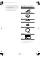
DTR-7.6,6.6.book Page 5 Monday, September 26, 2005 1:40 PM Contents Introduction Important Safety Instructions ....................2 Precautions .................................................3 Supplied Accessories.................................4 Features .......................................................6 Before Using the AV receiver ....................7 Getting to Know the AV Receiver ..............8 Remote Controller.....................................12 Connection Connecting Your Speakers .
DTR-7.6,6.6.book Page 6 Monday, September 26, 2005 1:40 PM Features DTR-7.6 and DTR-6.6 Amplifier • • • • 7-channel amplifier Optimum Gain Volume Circuitry WRAT (Wide Range Amplifier Technology) Massive High Current Power Supply (H.C.P.S.
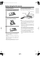
DTR-7.6,6.6.book Page 7 Monday, September 26, 2005 1:40 PM Before Using the AV receiver Installing the Batteries 1 To open the battery compartment, press the small hollow and slide open the cover. Using the Remote Controller To use the remote controller, point it at the AV receiver’s remote control sensor, as shown below. Remote control sensor Standby indicator AV receiver 30˚ 2 3 Insert the three supplied batteries (AA/R6) in accordance with the polarity diagram inside the battery compartment.
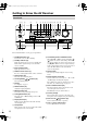
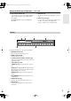
DTR-7.6,6.6.book Page 8 Monday, September 26, 2005 1:40 PM Getting to Know the AV Receiver Front Panel 12 3 4 P Q R 5 6 7 8 9 JK L M N S T O U V For detailed information, see the pages in parentheses. A Standby/On button (37) Sets the AV receiver to On or Standby. B Standby indicator (37) Lights up when the AV receiver is on Standby and flashes while a signal is being received from the remote controller. C Zone 2 indicator (80) Lights up when Zone 2 is on.
DTR-7.6,6.6.book Page 9 Monday, September 26, 2005 1:40 PM Getting to Know the AV Receiver—Continued T Input selector buttons (46) U Setup Mic (38) Select the following input sources: Multi CH, DVD, Video 1, Video 2, Video 3, Video 4, Tape, Tuner, CD, or Phono. The automatic speaker setup microphone connects here. V Video 4 Input (30, 60) The [Multi CH] button selects the multichannel DVD input. Used to connect a camcorder, game console, and so on.
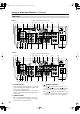
DTR-7.6,6.6.book Page 10 Monday, September 26, 2005 1:40 PM Getting to Know the AV Receiver—Continued Rear Panel DTR-7.6 7 Only on the North American model 123 4 5 P Q R S T 6 U 89J K V L W M O N X Y Z DTR-6.6 7 Only on the North American model 123 4 P Q R S T 6 U 89J K V A OPTICAL DIGITAL These optical digital audio inputs are for connecting components with optical digital audio outputs, such as CD players and DVD players.
DTR-7.6,6.6.book Page 11 Monday, September 26, 2005 1:40 PM Getting to Know the AV Receiver—Continued D COMPONENT VIDEO IN 1, 2, and 3 These RCA component video inputs are for connecting components with component video outputs, such as DVD players. E HDMI IN 1, 2, and OUT (DTR-7.6 only) HDMI (High Definition Multimedia Interface) connections carry digital audio and digital video. The HDMI inputs are for connecting components with HDMI outputs, such as DVD players.
DTR-7.6,6.6.book Page 12 Monday, September 26, 2005 1:40 PM Remote Controller About the Remote Controller Modes Including the AV receiver, the remote controller can be used to control up to nine different components. The remote controller has a specific operating mode for use with each type of component. Modes are selected by using the eight Remote Mode buttons. Receiver/Tape Mode Receiver/Tape mode is used to control the AV receiver.
DTR-7.6,6.6.book Page 13 Monday, September 26, 2005 1:40 PM Remote Controller—Continued For detailed information, see the pages in parentheses. T Muting button (54) Mutes or unmutes the AV receiver. A Standby button (37) Sets the AV receiver to Standby. B On button (37) Turns on the AV receiver. C Input Selector buttons (46) Used to select the input sources. D Multi CH button (53) Selects the multichannel DVD input. E Dimmer button (54) Adjusts the display brightness.
DTR-7.6,6.6.book Page 14 Monday, September 26, 2005 1:40 PM Remote Controller—Continued A Standby button DVD Mode Sets the DVD player to Standby. To set the remote controller to DVD mode, press the [DVD] Remote Mode button. B On button Turns on the DVD player. C Number buttons Used to enter title, chapter, and track numbers, and to enter times for locating specific points. D Top Menu button Selects a DVD’s top menu.
DTR-7.6,6.6.book Page 15 Monday, September 26, 2005 1:40 PM Remote Controller—Continued A Standby button CD, MD, and CDR Modes Sets the CD player or MD/CD recorder to Standby. To control an Integra CD player or a CD/MD recorder made by another manufacturer, press the [CD] Remote Mode button to select the CD remote controller mode. To control an Integra MD recorder or CD recorder, press the [MD] or [CDR] Remote Mode button to select the MD or CDR remote controller mode.
DTR-7.6,6.6.book Page 16 Monday, September 26, 2005 1:40 PM Remote Controller—Continued A Standby button HDD Mode Turns off the HDD-compatible component. HDD mode is for controlling Integra’s next generation HDD-compatible components. As of 2005, it can be used with the Onkyo DS-A1 Remote Interactive Dock and Apple iPod connected via . When Using the Onkyo DS-A1: • Connect the DS-A1 to the TAPE IN or VIDEO 3 IN jacks. • Set the DS-A1’s RI MODE switch to HDD.
DTR-7.6,6.6.book Page 17 Monday, September 26, 2005 1:40 PM Connecting Your Speakers Enjoying Home Theater Thanks to the AV receiver’s superb capabilities, you can enjoy surround sound with a real sense of movement in your own home—just like being in a movie theater or concert hall. You can enjoy DVDs featuring DTS and Dolby Digital. With analog and digital TV, you can enjoy Dolby Pro Logic IIx and Onkyo’s own DSP surround listening modes.
DTR-7.6,6.6.book Page 18 Monday, September 26, 2005 1:40 PM Connecting Your Speakers—Continued Connecting a Powered Subwoofer Connecting Your Speakers Speaker Configuration For the best surround-sound experience, you should connect seven speakers and a powered subwoofer. The following table shows which channels you should use based on the number of speakers you have.
DTR-7.6,6.6.book Page 19 Monday, September 26, 2005 1:40 PM Connecting Your Speakers—Continued Speaker Connection Precautions Read the following before connecting your speakers: • You can connect speakers with an impedance of between 4 and 16 ohms. If the impedance of any of the connected speakers is 4 ohms or more but less than 6, be sure to set the minimum speaker impedance to 4 ohms (see page 44).
DTR-7.6,6.6.book Page 20 Monday, September 26, 2005 1:40 PM Connecting Antenna This section explains how to connect the supplied indoor FM antenna and AM loop antenna, and how to connect commercially available outdoor FM and AM antennas. The AV receiver won’t pick up any radio signals without any antenna connected, so you must connect the antenna to use the tuner. AM antenna push terminals FM antenna jack Connecting the Indoor FM Antenna The supplied indoor FM antenna is for indoor use only.
DTR-7.6,6.6.book Page 21 Monday, September 26, 2005 1:40 PM Connecting Antenna—Continued Connecting an Outdoor FM Antenna Connecting an Outdoor AM Antenna If you cannot achieve good reception with the supplied indoor FM antenna, try a commercially available outdoor FM antenna instead. If good reception cannot be achieved using the supplied AM loop antenna, an outdoor AM antenna can be used in addition to the loop antenna, as shown.
DTR-7.6,6.6.book Page 22 Monday, September 26, 2005 1:40 PM Connecting Your Components AV Connection Color Coding About AV Connections RCA-type AV connections are usually color coded: red, white, and yellow. Use red plugs to connect right-channel audio inputs and outputs (typically labeled “R”). Use white plugs to connect left-channel audio inputs and outputs (typically labeled “L”). And use yellow plugs to connect composite video inputs and outputs.
DTR-7.6,6.6.book Page 23 Monday, September 26, 2005 1:40 PM Connecting Your Components—Continued Connecting Audio and Video Signals to the AV Receiver By connecting both the audio and video outputs of your DVD player and other AV components to the AV receiver, you can switch the audio and video signals simultaneously simply by changing the input source on the AV receiver. : Signal Flow Video Video Audio Audio TV, projector, etc. DVD player, etc.
DTR-7.6,6.6.book Page 24 Monday, September 26, 2005 1:40 PM Connecting Your Components—Continued Connecting a TV or Projector Step 1: Video Connection Choose a video connection that matches your TV ( A , B , or C ), and then make the connection. Step 2: Audio Connection Choose an audio connection that matches your TV ( a , b , or c ), and then make the connection. • With connection a , you can listen to and record audio from your TV and listen in Zone 2.
DTR-7.6,6.6.book Page 25 Monday, September 26, 2005 1:40 PM Connecting Your Components—Continued Connecting a DVD player Step 1: Video Connection Choose a video connection that matches your DVD player ( A , B , or C ), and then make the connection. If you use connection A , you must connect the AV receiver to your TV with the same type of connection. Step 2: Audio Connection Choose an audio connection that matches your DVD player ( a , b , or c ), and then make the connection.
DTR-7.6,6.6.book Page 26 Monday, September 26, 2005 1:40 PM Connecting Your Components—Continued Hooking Up the Multichannel DVD Input If your DVD player supports multichannel audio formats such as DVD-Audio or SACD, and it has a multichannel analog audio output, you can connect it to the AV receiver’s multichannel DVD input.
DTR-7.6,6.6.book Page 27 Monday, September 26, 2005 1:40 PM Connecting Your Components—Continued Connecting a VCR or DVD Recorder for Playback In addition to video playback, with this hookup, you can use your VCR’s tuner to listen to your favorite TV programs via the AV receiver, useful if your TV has no audio outputs. If you have two video recorders (e.g.
DTR-7.6,6.6.book Page 28 Monday, September 26, 2005 1:40 PM Connecting Your Components—Continued Connecting a VCR or DVD Recorder for Recording If you have two video recorders (e.g., a VCR and a DVD recorder), connect one recorder to the VIDEO 1 OUT jacks, as shown here, and connect the other recorder to the VIDEO 2 OUT jacks in the same way. Step 1: Video Connection Choose a video connection that matches your VCR or DVD recorder ( A or B ), and then make the connection.
DTR-7.6,6.6.book Page 29 Monday, September 26, 2005 1:40 PM Connecting Your Components—Continued Connecting a Satellite, Cable, Set-top box, or Other Video Source Step 1: Video Connection Choose a video connection that matches the video source ( A , B , or C ), and then make the connection. If you use connection A , you must connect the AV receiver to your TV with the same type of connection.
DTR-7.6,6.6.book Page 30 Monday, September 26, 2005 1:40 PM Connecting Your Components—Continued Connecting a Camcorder, Games Console, or Other Device Step 1: Video Connection Choose a video connection that matches the camcorder or console ( A or B ), and then make the connection. Step 2: Audio Connection Choose an audio connection that matches the camcorder or console ( a or b ), and then make the connection.
DTR-7.6,6.6.book Page 31 Monday, September 26, 2005 1:40 PM Connecting Your Components—Continued Connecting a CD Player Step 1: Choose a connection that matches your CD player ( a , b , or c ), and then make the connection. b c COAXIAL IN 2 OPTICAL IN 3 a IN L R CD Connect one or the other L COAXIAL OUT OPTICAL OUT R AUDIO OUT CD player • With connection a , you can listen to and record audio from the CD player and listen in Zone 2. • To connect the CD player digitally, use connection b or c .
DTR-7.6,6.6.book Page 32 Monday, September 26, 2005 1:40 PM Connecting Your Components—Continued Connecting a Cassette, CDR, MiniDisc, or DAT Recorder Step 1: Choose a connection that matches the recorder ( a , b , c , or d ), and then make the connection. b a IN COAXIAL IN 2 L R c TAPE OPTICAL a IN 4 L d OPTICAL R TAPE Connect one or the other L COAXIAL OUT OPTICAL OUT OPTICAL IN R AUDIO IN L R AUDIO OUT Cassette, CDR, MD, etc.
DTR-7.6,6.6.book Page 33 Monday, September 26, 2005 1:40 PM Connecting Your Components—Continued Connecting Components Step 1: Make sure that each Integra component is connected to the AV receiver with an analog audio cable (RCA). Step 2: Make the With connection.
DTR-7.6,6.6.book Page 34 Monday, September 26, 2005 1:40 PM Connecting Your Components—Continued Connecting Components with HDMI (DTR-7.6 Only) About HDMI Designed to meet the demands of digital TV, HDMI (High Definition Multimedia Interface) is a new digital interface standard for connecting TVs, projectors, DVD players, set-top boxes, and other video components. Until now, several separate video and audio cables have been required to connect AV components.
DTR-7.6,6.6.book Page 35 Monday, September 26, 2005 1:40 PM Connecting Your Components—Continued Making HDMI Connections Step 1: Use HDMI cables to connect the DTR-7.6’s HDMI jacks to your HDMI-compatible DVD player, TV, projector, and so on. Step 2: Assign each HDMI IN to an input selector in the HDMI Video setup (see page 41). Video Signal Flow Chart Digital video signals received at HDMI IN 1 and 2 are only output by the HDMI OUT and sent to your TV.
DTR-7.6,6.6.book Page 36 Monday, September 26, 2005 1:40 PM Connecting Your Components—Continued Connecting the Power Cords of Other Components The AV receiver has AC outlets on its rear panel that can be used to connect the power cords of other components that you intend to use with the AV receiver. These components can then be left turned on so that they turn on and off as and when the AV receiver is turned on and set to Standby. AC OUTLETS AC 120 V 60 Hz SWITCHED TOTAL 120W 1A MAX.
DTR-7.6,6.6.book Page 37 Monday, September 26, 2005 1:40 PM Turning On the AV Receiver Standby/On Standby indicator Standby On Receiver Turning On and Standby Remote controller AV receiver or Press the [Standby/On] button. Alternatively, press the remote controller’s [Receiver] button, followed by the [On] button. The AV receiver comes on, the display lights up, and the Standby indicator goes off. Pressing the remote controller’s [On] button again will turn on any components connected via .
DTR-7.6,6.6.book Page 38 Monday, September 26, 2005 1:40 PM First Time Setup This section explains the settings that you need to make before using the AV receiver for the very first time. 2 Put the speaker setup microphone in the listening position.
DTR-7.6,6.6.book Page 39 Monday, September 26, 2005 1:40 PM First Time Setup—Continued 3 Press [Enter]. The automatic speaker setup starts. The test tone is output by each speaker in turn. The microphone picks up the sound and feeds it back to the AV receiver, where it’s used to calculate the optimum speaker settings. The whole process takes about 2 minutes. 5 Disconnect the speaker setup microphone. Auto Speaker Setup ======================= Please,unplug Setup Mic.
DTR-7.6,6.6.book Page 40 Monday, September 26, 2005 1:40 PM First Time Setup—Continued ■ Checking the Results If you selected “Check the Results” in step 4 on the previous page, the following menu appears and you can check the results of the automatic speaker setup. Auto Speaker Setup ======================== 1.Warning 2.Speaker Config 3.Speaker Distance 4.Speaker Level Adjust 5.Equalizer Settings When you’ve finished checking, press the [Return] button to return to the menu in step 4.
DTR-7.6,6.6.book Page 41 Monday, September 26, 2005 1:40 PM First Time Setup—Continued HDMI Video Setup (DTR-7.6 Only) 1 Press the [Receiver] button, followed by the [Setup] button. The main menu appears onscreen. 2 Use the Up and Down [ ]/[ ] buttons to select “0.HDMI Video,” and then press [Enter]. The HDMI Video menu appears. 0.HDMI Video -----------------------a.DVD :No b.VIDEO1 :No c.VIDEO2 :No d.VIDEO3 :No e.
DTR-7.6,6.6.book Page 42 Monday, September 26, 2005 1:40 PM First Time Setup—Continued Component Video Setup 1 Press the [Receiver] button, followed by the [Setup] button. The main menu appears onscreen. 2 Use the Up and Down [ ]/[ ] buttons to select “1. Component Video,” and then press [Enter]. The Component Video menu appears. 1.Component Video -----------------------a.DVD :IN1 b.VIDEO1 :VIDEO c.VIDEO2 :VIDEO d.VIDEO3 :VIDEO e.
DTR-7.6,6.6.book Page 43 Monday, September 26, 2005 1:40 PM First Time Setup—Continued Digital Audio Input Setup 1 Press the [Receiver] button, followed by the [Setup] button. The main menu appears onscreen. 2 Use the Up and Down [ ]/[ ] buttons to select “2. Digital Input,” and then press [Enter]. The Digital Input menu appears. 2.Digital Input -----------------------a.DVD :Coax1 b.VIDEO1 :Opt1 c.VIDEO2 :No d.VIDEO3 :Opt2 e.VIDEO4 :Front f.TAPE :No g.CD :Opt3 h.
DTR-7.6,6.6.book Page 44 Monday, September 26, 2005 1:40 PM First Time Setup—Continued Changing the Input Display If you connect an -capable Integra MiniDisc recorder, CD recorder, or next generation HDD-compatible component to the TAPE IN/OUT or VIDEO 3 IN jacks, for to work properly, you must change this setting. This setting can only be changed on the AV receiver. 1, 2 1 Minimum Speaker Impedance If you change this setting, you must run the automatic speaker setup again (see page 38).
DTR-7.6,6.6.book Page 45 Monday, September 26, 2005 1:40 PM First Time Setup—Continued TV Format Setup (not North American models) You must specify the TV system used in your area. 1 2 Press the [Receiver] button, followed by the [Setup] button. The main menu appears onscreen. Use the Up and Down [ ]/[ ] buttons to select “8. Hardware Setup,” and then press [Enter]. The Hardware Setup menu appears. AM Frequency Step Setup (on some models) You must specify the AM frequency step used in your area.
DTR-7.6,6.6.book Page 46 Monday, September 26, 2005 1:40 PM Playing Your AV Components Basic AV Receiver Operation 3 1 1 1 3 1 Remote controller AV receiver Use the AV receiver’s input selector buttons to select the input source. To select the input source with the remote controller, press the [Receiver] Remote Mode button, and then use the Input Selector buttons.
DTR-7.6,6.6.book Page 47 Monday, September 26, 2005 1:40 PM Listening to the Radio ■ Manual Tuning Mode Listening to AM/FM Stations Tuning Mode Tuning 1 Press the [Tuning Mode] button so that the AUTO indicator disappears from the display. 2 Press and hold the Tuning Up or Down [ ]/[ ] button. The frequency stops changing when you release the button. Press the buttons repeatedly to change the frequency one step at a time.
DTR-7.6,6.6.book Page 48 Monday, September 26, 2005 1:40 PM Listening to the Radio—Continued Listening to XM Satellite Radio® (only for North American model) What’s XM Satellite Radio? There is a world beyond AM and FM. It is XM Satellite Radio. XM offers more than 150 digital channels of audio entertainment, including 100% commercial-free music channels, in the top markets in the U.S. Note: An XM Connect-and-Play™ antenna and monthly subscription are required to receive XM Satellite Radio. Visit www.
DTR-7.6,6.6.book Page 49 Monday, September 26, 2005 1:40 PM Listening to the Radio—Continued ■ Category Search Mode Selecting XM Radio Channels There are two modes for selecting XM radio channels: Channel Search mode, which allows you to select any channel. Category Search mode, which allows you to select channels by category. 1 1 1 Press the [Receiver] Remote Mode button, and then press the [Tuner] Input Selector button repeatedly to select XM.
DTR-7.6,6.6.book Page 50 Monday, September 26, 2005 1:40 PM Listening to the Radio—Continued Display / Receiver Display Tuner Return Selecting XM Channels from the Front Panel: 1 Press the [Tuner] input selector button repeatedly to select XM. If “CHECK ANTENNA” appears on the display, make sure the XM antenna is connected properly. 2 Use the Tuning Up and Down [ ]/[ ] buttons to select a channel. In Channel Search mode, you can select any channel.
DTR-7.6,6.6.book Page 51 Monday, September 26, 2005 1:40 PM Listening to the Radio—Continued 4 Adjust the position of the XM antenna so that the “Signal Quality” is at least 70%. 4-3.XM Antenna Aiming -------TUNER------------a.Signal Quality :100% [ | ] The signal quality range is 0% to 100%. 1 5 2, 3 1, 5 Positioning the XM Antenna You can check the signal strength of the XM radio signal and adjust the position of the XM antenna accordingly.
DTR-7.6,6.6.book Page 52 Monday, September 26, 2005 1:40 PM Listening to the Radio—Continued Presetting AM/FM Stations and XM Channels 2, 4 Selecting Presets 1 3 You can store a combination of up to 40 of your favorite AM/FM radio stations and XM channels as presets. 52 1 Tune into the AM/FM station or XM channel that you want to store as a preset. 2 Press the [Memory] button. The MEMORY indicator appears and the preset number flashes.
DTR-7.6,6.6.book Page 53 Monday, September 26, 2005 1:40 PM Using the Multichannel DVD Input Multichannel DVD Input Settings 1 While the DVD input is selected, press the [Receiver] Remote Mode button, followed by the [Setup] button. The main menu appears onscreen. 2 Use the Up and Down [ ]/[ ] buttons to select “4. Input Setup,” and then press [Enter]. Multi CH Receiver Use the Up and Down [ ]/[ ] buttons to select “3. MULTICH,” and then press [Enter]. The MULTICH menu appears. Enter Setup 4-3.
DTR-7.6,6.6.book Page 54 Monday, September 26, 2005 1:40 PM Common Functions This section explains functions that can be used with any input source. Adjusting Speaker Levels You can adjust the volume of each speaker while listening to an input source. These temporary adjustments are cancelled when the AV receiver is set to Standby.
DTR-7.6,6.6.book Page 55 Monday, September 26, 2005 1:40 PM Common Functions—Continued Using the Sleep Timer With the sleep timer, you can set the AV receiver so that it turns off automatically after a specified period. Press the remote controller’s [Sleep] button repeatedly to select the required sleep time. You can set the sleep time from 90 to 10 minutes in 10 minute steps. The SLEEP indicator appears on the display when the sleep timer has been set, as shown.
DTR-7.6,6.6.book Page 56 Monday, September 26, 2005 1:40 PM Using the Listening Modes Selecting the Listening Modes Selecting with the Remote Controller For a description of each listening mode, see “About the Listening Modes” on page 58. • The Dolby Digital and DTS listening modes can only be selected if your DVD player is connected to the AV receiver with a digital audio connection (coaxial, optical, or HDMI). • Listening mode availability depends on the format of the current input signal.
DTR-7.6,6.6.book Page 57 Monday, September 26, 2005 1:40 PM Using the Listening Modes—Continued The following table shows which listening modes can be used with each input signal format. Source format 3/2.1 2/2.1 CD, TV, radio, cassette, etc. Listening mode DTS/DTS 96/24*2 Dolby Digital Analog, PCM*1 2/0 1/0, 1+1 Other 3/2.1 2/2.1 DVD, DTV, etc. DTS-ES 2/0 Discrete Matrix DVD, CD, etc.
DTR-7.6,6.6.book Page 58 Monday, September 26, 2005 1:40 PM Using the Listening Modes—Continued About the Listening Modes The AV receiver’s listening modes can transform your listening room into a movie theater or concert hall, with high fidelity and stunning surround sound. Direct In this mode, audio from the input source is output directly with minimal processing, providing high-fidelity reproduction. All of the source’s audio channels are output as they are.
DTR-7.6,6.6.book Page 59 Monday, September 26, 2005 1:40 PM Using the Listening Modes—Continued THX Onkyo Original DSP Modes Founded by George Lucas, THX develops stringent standards that ensure movies are reproduced in movie theaters and home theaters just as the director intended. Mono Movie • THX Cinema This mode is for watching movies, which are typically recorded and edited on the assumption that they will be played in a sizable place like a movie theater.
DTR-7.6,6.6.book Page 60 Monday, September 26, 2005 1:40 PM Recording This section explains how to record the input source and how to record audio and video from separate sources. Notes: • The surround sound and DSP listening modes cannot be recorded. • Copy-protected DVDs cannot be recorded. • Sources connected to the multichannel DVD input cannot be recorded. • Various restrictions apply to digital recording. Refer to the manuals supplied with your digital recording equipment for more details.
DTR-7.6,6.6.book Page 61 Monday, September 26, 2005 1:40 PM Onscreen Setup Menus About the Onscreen Setup Menus The onscreen setup menus are displayed on the connected TV (not via the HDMI OUT) and provide a convenient way to change the AV receiver’s settings, which are arranged into two groups: First Time Setup and Advanced Setup. To get your system up and running, you must complete the First Time Setup settings.
DTR-7.6,6.6.book Page 62 Monday, September 26, 2005 1:40 PM Adjusting the Listening Modes Audio Adjust Menu The Audio Adjust menu has various settings for adjusting the sound and listening modes. 1 Press the [Receiver] Remote Mode button, followed by the [Setup] button. The main menu appears onscreen. 2 Use the Up and Down [ ]/[ ] buttons to select “6. Audio Adjust,” and then press [Enter]. The Audio Adjust menu appears. Receiver Enter 6.Audio Adjust -----------------------1.Tone Control 2.
DTR-7.6,6.6.book Page 63 Monday, September 26, 2005 1:40 PM Adjusting the Listening Modes—Continued Tone Control Settings PL IIx and Neo:6 Settings You can adjust the bass and treble for the front speakers. The tone control circuits are bypassed in the Direct listening mode. These settings only apply to 2-channel (stereo) sources. ■ Bass You can boost or cut low-frequency sounds output by the front speakers from –10 dB to +10 dB in 1 dB steps.
DTR-7.6,6.6.book Page 64 Monday, September 26, 2005 1:40 PM Adjusting the Listening Modes—Continued Dolby Digital Settings Mono/Multiplex Settings ■ Dolby EX This setting determines how Dolby Digital EX signals are handled. This setting is unavailable if no surround back speakers are connected or the ZONE 2 SPEAKERS terminals are being used (page 78). Auto: Dolby Digital EX can be selected from among the Dolby listening modes, and THX Surround EX can be selected from among the THX listening modes.
DTR-7.6,6.6.book Page 65 Monday, September 26, 2005 1:40 PM Adjusting the Listening Modes—Continued Default Listening Modes 4 Use the Up and Down [ ]/[ ] buttons to select a signal format, and then use the Left and Right [ ]/[ ] buttons to select a listening mode. Only listening modes compatible with each signal format can be selected. The signal formats are explained below. 5 When you’ve finished, press the [Setup] button. Setup closes.
DTR-7.6,6.6.book Page 66 Monday, September 26, 2005 1:40 PM Advanced Setup Speaker Setup 2 Use the Up and Down [ ]/[ ] buttons to select “3. Speaker Setup,” and then press [Enter]. The Speaker Setup menu appears. 3 Use the Up and Down [ ]/[ ] buttons to select “Speaker Configuration,” and then press [Enter]. The Speaker Config menu appears.
DTR-7.6,6.6.book Page 67 Monday, September 26, 2005 1:40 PM Advanced Setup—Continued 7 8 9 Use the Up and Down [ ]/[ ] buttons to select “d. Surround,” and then use the Left and Right [ ]/[ ] buttons to select a crossover frequency. If no surround left and right speakers are connected, select None. Note: • If the Front setting in step 5 is set to anything other than Full Band, Full Band cannot be selected here. Use the Up and Down [ ]/[ ] buttons to select “e.
DTR-7.6,6.6.book Page 68 Monday, September 26, 2005 1:40 PM Advanced Setup—Continued Speaker Distance 4 Use the Up and Down [ ]/[ ] buttons to select “a. Unit,” and then use the Left and Right [ ]/[ ] buttons to select: feet: Select if you want to enter distances in feet. Can be set from 1 to 30 feet in 0.5-foot steps. meters: Select if you want to enter distances in meters. Can be set from 0.3 to 9 meters in 0.15-meter steps.
DTR-7.6,6.6.book Page 69 Monday, September 26, 2005 1:40 PM Advanced Setup—Continued Speaker Level Calibration 3 These settings are set automatically by the Automatic Speaker Setup function (see page 38). With these settings, you can adjust the level of each speaker while listening to the test tone so that the volume of each speaker is the same at the listening position. Notes: • The speakers cannot be calibrated while the output of the AV receiver is muted or a pair of headphones is connected.
DTR-7.6,6.6.book Page 70 Monday, September 26, 2005 1:40 PM Advanced Setup—Continued THX Audio Setup 4 Use the Left and Right [ ]/[ ] buttons to specify the surround back speaker spacing: 0–1 ft (0–0.3 m) (Default): Select this if the speakers are between 0 and 1 foot (0–30 cm) apart. 1–4 ft (0.3–1.2 m): Select this if the speakers are between 1 and 4 feet (0.3–1.2 m) apart. >4 ft (>1.2 m): Select this if the speakers are more than 4 feet (1.2 m) apart. 5 Press the [Setup] button.
DTR-7.6,6.6.book Page 71 Monday, September 26, 2005 1:40 PM Advanced Setup—Continued Equalizer Settings 5 These settings are set automatically by the Automatic Speaker Setup function (see page 38). With these settings, you can adjust the tone of each speaker. The volume of each speaker can be set on page 69. 1 2 3 4 3-6.Equalizer Settings -----------------------a.Use Settings:Manual -----------------------b.Channel :Left -----------------------c. 80Hz : 0dB d. 250Hz : 0dB e. 800Hz : 0dB f.2.
DTR-7.6,6.6.book Page 72 Monday, September 26, 2005 1:40 PM Advanced Setup—Continued Input Setup 3 This section explains items on the “Input Setup” menu. Use the Up and Down [ ]/[ ] buttons to select “Delay,” and then press [Enter]. The Delay menu appears. 4-1.Delay ---------VIDEO1--------a.A/V Sync : 45ms Press Enter to see picture while adjusting. Receiver Press Return to return to setup.
DTR-7.6,6.6.book Page 73 Monday, September 26, 2005 1:40 PM Advanced Setup—Continued Character Edit With this setting, you can enter a custom name for each input source. When the input source is selected, its name will appear on the display. 1 Press the [Receiver] Remote Mode button, followed by the [Setup] button. The main menu appears onscreen. 2 Use the Up and Down [ ]/[ ] buttons to select “4. Input Setup,” and then press [Enter]. The Input Setup menu appears.
DTR-7.6,6.6.book Page 74 Monday, September 26, 2005 1:40 PM Advanced Setup—Continued Preferences 4 Use the Up and Down [ ]/[ ] buttons to select an option, and use the Left and Right [ ]/[ ] buttons to change it. The preferences are explained in the next column. 5 When you’ve finished, press the [Setup] button. Setup closes. This section explains items on the “Preference” menu.
DTR-7.6,6.6.book Page 75 Monday, September 26, 2005 1:40 PM Advanced Setup—Continued ■ Power On Vol / Z2 Power On Vol With these preferences, you can specify the volume settings to be used in the main room and Zone 2 when the AV receiver is turned on. When the Volume Display preference is set to Absolute, the range of “Power On Vol” is 0 to 100 (“Z2 Power On Vol” is 0 to 82). When it’s set to Relative, the range of “Power On Vol” is –∞ dB, –81 dB to +18 dB (“Z2 Power On Vol” is –∞ dB, –81 dB to 0 dB).
DTR-7.6,6.6.book Page 76 Monday, September 26, 2005 1:40 PM Advanced Setup—Continued Remote IDs 3 Use the Up and Down [ ]/[ ] buttons to select “Remote ID,” and use the Left and Right [ ]/[ ] buttons to select ID 1, 2, or 3. Remote indicator TV INPUT 8.Hardware Setup -----------------------a.PoweredZone2:NotAct b.Zone2 Out :Fixed c.TV Format :Auto d.AM Freq. Step: 9kHz e.Remote ID :1 Number buttons Receiver 4 Press the [Setup] button. Setup closes.
DTR-7.6,6.6.book Page 77 Monday, September 26, 2005 1:40 PM Advanced Setup—Continued Digital Input Signal Formats 3 Normally, the AV receiver detects the signal format automatically. However, if you experience either of the following issues when playing PCM or DTS material, you can specify the signal format as either PCM or DTS: • If the beginnings of tracks from a PCM source are cut off, try the PCM setting. • If noise is produced when fast forwarding or rewinding a DTS CD, try the DTS setting. 2-1.
DTR-7.6,6.6.book Page 78 Monday, September 26, 2005 1:40 PM Zone 2 Using Only Speakers in Zone 2 Connecting Zone 2 With the Zone 2 function, you can enjoy one input source in the main room and a different input source in another room. There are two ways to hook up your Zone 2 speakers: 1) Use another amp (receiver, integrated amp, or power amp) in Zone 2 and connect your Zone 2 speakers to it. 2) Connect your Zone 2 speakers to this AV receiver. With this hookup, you can enjoy 5.
DTR-7.6,6.6.book Page 79 Monday, September 26, 2005 1:40 PM Zone 2—Continued Powered Zone 2 Setting If you’ve connected your Zone 2 speakers to this AV receiver, as explained in “Using Only Speakers in Zone 2” on page 78, you must set the Powered Zone 2 setting to Act (Activated) as explained here. 1 2 3 Press the [Receiver] Remote Mode button, followed by the [Setup] button. The main menu appears onscreen. Use the Up and Down [ ]/[ ] buttons to select “8. Hardware Setup,” and then press [Enter].
DTR-7.6,6.6.book Page 80 Monday, September 26, 2005 1:40 PM Zone 2—Continued Using Zone 2 Controlling Zone 2 with the Remote Controller This section explains how to turn Zone 2 on and off, how to select an input source for Zone 2, and how to adjust the volume for Zone 2. Standby On Controlling Zone 2 from the AV Receiver Input Selector 1 2 Zone2 1 Level–, Level+ To turn on Zone 2 and select an input source, press the [Zone 2] button repeatedly.
DTR-7.6,6.6.book Page 81 Monday, September 26, 2005 1:40 PM Zone 2—Continued Adjusting the Volume for Zone 2 Adjusting the Tone and Balance for Zone 2 You can adjust the bass, treble, and balance for Zone 2. Zone 2 Level , 1 2 1 On the remote controller, press the [Zone 2] Remote Mode button, and then use the [Level–] and [Level+] buttons. AV receiver On the AV receiver, use the Zone 2 Level [ ]/[ ] buttons. The volume can be set to –∞ dB, –81 dB –80 dB through 0 dB in Relative display (Min.
DTR-7.6,6.6.book Page 82 Monday, September 26, 2005 1:40 PM Zone 2—Continued Using the 12V Triggers in Zone 2 and the Main Room When the AV receiver’s 12 V TRIGGER OUT A/B/C jack is connected to the 12 V trigger input on a connected component, you can specify whether or not a 12volt trigger signal is output when that component is selected as the source for the main room, Zone 2, or either.
DTR-7.6,6.6.book Page 83 Monday, September 26, 2005 1:40 PM Zone 2—Continued Using the Remote Controller in Zone 2 and Multiroom Control Kits To control the AV receiver with the remote controller while you’re in the Zone 2 room, you’ll need a commercially available multiroom remote control kit. • Multiroom kits are made by Niles and Xantech. These kits can also be used when there isn’t a clear line of sight to the AV receiver’s remote sensor, such as when it’s installed inside a cabinet.
DTR-7.6,6.6.book Page 84 Monday, September 26, 2005 1:40 PM Controlling Other Components You can control your other components, including those made by other manufacturers, with the remote controller. This section explains how to: • Enter the remote control code for a component that you want to control (e.g., DVD, TV, VCR). • Learn commands directly from another component’s remote controller (see page 87). • Program the Macro buttons to perform a sequence of up to eight actions (see page 88).
DTR-7.6,6.6.book Page 85 Monday, September 26, 2005 1:40 PM Controlling Other Components—Continued Remote Control Codes for Integra Components Connected via Integra components that are connected via are controlled by pointing the remote controller at the AV receiver, not the component. This allows you to control components that are out of view, in a rack, for example. 1 Make sure the Integra component is connected with an cable and an analog audio cable (RCA). See page 33 for details.
DTR-7.6,6.6.book Page 86 Monday, September 26, 2005 1:40 PM Controlling Other Components—Continued To control another component, point the remote controller at it and use the buttons explained below. (You must select the appropriate remote control mode first.) With some AV components, certain buttons may not work as expected, and some may not work at all.
DTR-7.6,6.6.book Page 87 Monday, September 26, 2005 1:40 PM Controlling Other Components—Continued 3 VD D PO D C PE TA C IS D D C -1 VID EO IM D P EE SL ER W CH TI- T UL PU M IN RE SUOD M O Remote indicator ER About 2 to 6 inches (5–15 cm) O N R O T TO H SE C P ER E LE R N PR SE E TU T UN PU T IN P U PE O R TA G VD D -2 EO VID C H SE L E EV ST E TEON T L M U TIN G VO LU M E R The AV receiver’s remote controller can receive and learn commands from other remote controllers.
DTR-7.6,6.6.book Page 88 Monday, September 26, 2005 1:40 PM Controlling Other Components—Continued Using Macros 1 You can program the remote controller’s Macro buttons to perform a sequence of actions. Example: To play a CD, you typically need to perform the following actions: 1. Press the [Receiver] Remote Mode button to select the Receiver remote controller mode. 2. Press the [On] button to turn on the AV receiver. 3. Press the [CD] Input Selector button to select the CD input source. 4.
DTR-7.6,6.6.book Page 89 Monday, September 26, 2005 1:40 PM Troubleshooting If you have any trouble using the AV receiver, look for a solution in this section. If you can’t resolve the issue yourself, contact the dealer from whom you purchased. Power Can’t turn on the AV receiver • Make sure that the power cord is plugged into the wall outlet properly. • Unplug the power cord from the wall outlet, wait 5 seconds or more, then plug it in again.
DTR-7.6,6.6.book Page 90 Monday, September 26, 2005 1:40 PM Troubleshooting—Continued The subwoofer produces no sound • When you play source material that contains no information in the LFE channel, the subwoofer produces no sound. • Make sure the speakers are configured correctly (pages 66, 67). The Zone 2 speakers produce no sound • The Zone 2 speakers only output sources that are connected to an analog input. Check to see if the source is connected to an analog input.
DTR-7.6,6.6.book Page 91 Monday, September 26, 2005 1:40 PM Troubleshooting—Continued The immediate display does not appear • The immediate display does not appear on a TV that’s connected to the HDMI OUT or COMPONENT VIDEO OUT. Tuner Reception is noisy, stereo FM reception suffers from hiss, or the FM STEREO indicator doesn’t appear • Relocate your antenna. • Move the AV receiver away from your TV or computer. • Listen to the station in mono (page 47).
DTR-7.6,6.6.book Page 92 Monday, September 26, 2005 1:40 PM Troubleshooting—Continued The AV receiver contains a microcomputer for signal processing and control functions. In very rare situations, severe interference, noise from an external source, or static electricity may cause it to lockup. In the unlikely event that this happens, unplug the power cord from the wall outlet, wait at least five seconds, and then plug it back in again.
DTR-7.6,6.6.book Page 93 Monday, September 26, 2005 1:40 PM Specification Amplifier Section General Power Output DTR-7.6: 2 channels driven: Power Supply DTR-6.6: 2 channels driven: Dynamic Power DTR-7.6: DTR-6.
DTR-7.6,6.6.
DTR-7.6,6.6.
DTR-7.6,6.6.book Page 96 Monday, September 26, 2005 1:40 PM Integra Division of ONKYO U.S.A. CORPORATION 18 park Way, Upper Saddle River, N.J. 07458, U.S.A. Tel: 201-785-2600 Fax: 201-785-2650 http://www.integrahometheater.com Integra Division of ONKYO CORPORATION Sales & Product Planning Div.: 2-1, Nisshin-cho, Neyagawa-shi, OSAKA 572-8540, JAPAN Tel: 072-831-8023 Fax: 072-831-8124 En I0509-1 SN 29344081 (C) Copyright 2005 ONKYO CORPORATION Japan. All rights reserved.