AV Receiver DTR-7.
Thank you for purchasing an Integra AV Receiver. Please read this manual thoroughly before making connections and plugging in the unit. Following the instructions in this manual will enable you to obtain optimum performance and listening enjoyment from your new AV Receiver. Please retain this manual for future reference. WARNING: TO REDUCE THE RISK OF FIRE OR ELECTRIC SHOCK, DO NOT EXPOSE THIS APPARATUS TO RAIN OR MOISTURE. CAUTION: TO REDUCE THE RISK OF ELECTRIC SHOCK, DO NOT REMOVE COVER (OR BACK).
Precautions 1. Recording Copyright—Unless it’s for personal use only, recording copyrighted material is illegal without the permission of the copyright holder. 2. AC Fuse—The AC fuse inside the unit is not userserviceable. If you cannot turn on the unit, contact the dealer from whom you purchased this unit.. 3. Care—Occasionally you should dust the unit all over with a soft cloth. For stubborn stains, use a soft cloth dampened with a weak solution of mild detergent and water.
Precautions—Continued For British models Replacement and mounting of an AC plug on the power supply cord of this unit should be performed only by qualified service personnel.
Contents Features ............................................................ 6 Supplied Accessories ...................................... 7 Multiroom Capability ........................................ 8 Getting to Know the AV Receiver ................... 9 Front Panel ...................................................................9 Display .......................................................................11 Rear Panel ..................................................................
Features Amplifier Tuner • 7-channel amplifier • 130 watts minimum continuous power per channel, 8 ohm loads, 2 channels driven from 20 Hz to 20 kHz, with a maximum total harmonic distortion of 0.08% (FTC) • Linear Optimum Gain Volume Circuitry • Powered Zone 2 capability • Bi-amp capability for front speakers • WRAT (Wide Range Amplifier Technology) • Massive High Current Power Supply (H.C.P.S.) transformer • Color-coded speaker terminal posts • XM*8 Satellite Radio ready (N.
Features—Continued Supplied Accessories Make sure you have the following accessories: *9 ©2005 SIRIUS Satellite Radio Inc. “SIRIUS,” SiriusConnect, the SIRIUS dog logo, channel names and logos are trademarks of SIRIUS Satellite Radio Inc. Available only in the contiguous United States (excluding Alaska and Hawaii) and Canada. *10 Remote controller and three batteries (AA/R6) Manufactured under license from Audyssey Laboratories. U.S. and foreign patents pending.
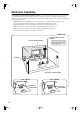
Multiroom Capability You can use three speaker systems with this AV receiver—a surround-sound speaker system (up to 7.1 channels) in your main listening room, a stereo speaker system in a second room, or Zone 2, as we call it, and another stereo speaker system in a third room that we call Zone 3 (external power amplifier required). And, you can select a different audio source for each room. Main Room: In your main listening room, you can enjoy up to 7.1-channel playback (see pages 21–22).
Getting to Know the AV Receiver Front Panel North American model 1 2 Q R 45 6 S T 7 8 9J K L MN O U V W P X Other models 3 J The actual front panel has various logos printed on it. They are not shown here for clarity. For detailed information, see the pages in parentheses. A Standby/On button (43) Sets the AV receiver to On or Standby. B Standby indicator (43) Lights up when the AV receiver is on Standby and flashes while a signal is being received from the remote controller.
Getting to Know the AV Receiver—Continued E Zone 3 indicator (115) Flashes when Zone 3 is being set. Lights up when Zone 3 is on. F Remote-control sensor (14) Receives control signals from the remote controller. G Stereo button (82) Selects the Stereo listening mode. H Listening Mode [ ]/[ ] buttons (82) Select the listening modes. I Display See “Display” on page 11. J Dimmer (RT/PTY/TP) button (64, 79) Adjusts the display brightness.
Getting to Know the AV Receiver—Continued Display 1 2 6 3 7 4 8 9 0 5 A For detailed information, see the pages in parentheses. 1 Speaker/channel indicators (87) Indicate the speaker configuration and channels used by the current input source. – : A box is displayed for each speaker that’s set in the Speaker Configuration. No box appears for speakers that are set to No or None. The following abbreviations indicate which audio channels are included in the current input signal.
Getting to Know the AV Receiver—Continued Rear Panel North American model only 678 9 12 34 5 J K LM N O P Q HDMI AC INLET ASSIGNABLE IN 3 RS232 IN 2 IN 1 OUT XM COMPONENT VIDEO IN 3 ASSIGNABLE IN 1(DVD) MONITOR IN 2 MONITOR OUT 2 /ZONE 2 OUT ETHERNET ANTENNA AM SIRIUS FM75 OUT 1 Y V REMOTE CONTROL DIGITAL AUX 1 GAME/TV CBL/SAT VCR/DVR DVD MONITOR OUT V CB/PB IR A IN ZONE 2 OUT B C 12V TRIGGER OUT ASSIGNABLE ZONE 2 COAXIAL IN 1 (DVD) S S IN IN 2 (VCR/DVR) IN 3
Getting to Know the AV Receiver—Continued N IR IN A/B and OUT A commercially available IR receiver can be connected to the IR IN A or B jack, allowing you to control the AV receiver while you’re in Zone 2, or control it when it’s out of sight, for example, installed in a cabinet. A commercially available IR emitter can be connected to the IR OUT jack to pass IR (infrared) remote control signals through to other components.
Remote Controller Installing the Batteries 1 To open the battery compartment, press the small hollow and slide open the cover. Using the Remote Controller When using the remote controller, point it toward the AV receiver’s remote control sensor, as shown below. Remote control sensor Standby indicator AV receiver 30˚ 2 3 Insert the three supplied batteries (AA/R6) in accordance with the polarity diagram inside the battery compartment. Slide the cover shut.
Remote Controller—Continued About the Remote Controller Modes As well as the AV receiver, you can also use the remote controller to control your other AV components. The remote controller has a specific operating mode for use with each type of component. Modes are selected by using the Remote Mode buttons. Receiver/Tape Mode Receiver/Tape mode is used to control the AV receiver. It can also be used to control an Onkyo cassette recorder connected via .
Remote Controller—Continued For detailed information, see the pages in parentheses. T L Night button (91) Turns the Late Night function on or off. A Standby button (43) Sets the AV receiver to Standby. B On button (43) U Audio Sel button (81) Selects the audio input: analog, digital, HDMI, or multichannel. Turns on the AV receiver. C Input Selector buttons (60) Used to select the input source. D Macro buttons (123) Used with the Macro function. E Dimmer button (79) Adjusts the display brightness.
Remote Controller—Continued A Standby button DVD Mode Sets the DVD player to Standby. To set the remote controller to DVD mode, press the [DVD] Remote Mode button. B On button Turns on the DVD player. C Number buttons Used to enter title, chapter, and track numbers, and to enter times for locating specific points. D Top Menu button Selects a DVD’s top menu. A B C E Arrow [ ]/[ ]/[ ]/[ ] and Enter buttons On Standby DVD VCR/DVR Used to navigate menus and select items.
Remote Controller—Continued A Standby button CD/MD/CDR Modes Sets the component to Standby. To control an Integra/Onkyo CD player, MD recorder, or CD recorder, or a CD or MD player/recorder made by another manufacturer, press the [CD] Remote Mode button to select the CD/MD/CDR remote controller mode. In order to control an Onkyo MD recorder or CD recorder, or a component made by another manufacturer, you must first enter the appropriate remote control code (see page 119).
Remote Controller—Continued A Standby button Dock Mode Turns off the iPod. Dock mode is for controlling an Apple iPod in an Onkyo RI Dock. When Using an RI Dock: • Connect the RI Dock to the TAPE IN or GAME/TV IN L/R jacks. • Set the RI Dock’s RI MODE switch to HDD or HDD/DOCK. • Set the AV receiver’s Input Display to DOCK (see page 49). • When operating a DS-A1 RI Dock, enter the appropriate remote control code for the first time (see page 119).
Connecting Your Speakers Enjoying Home Theater Thanks to the AV receiver’s superb capabilities, you can enjoy surround sound with a real sense of movement in your own home—just like being in a movie theater or concert hall. You can enjoy DVDs featuring Dolby Digital or DTS. With analog or digital TV, you can enjoy Dolby Pro Logic IIx, DTS Neo:6, or Onkyo’s original DSP listening modes. You can also enjoy THX Surround EX (THX-certified THX speaker system recommended).
Connecting Your Speakers—Continued Connecting a Powered Subwoofer Connecting Your Speakers Speaker Configuration For the best surround-sound experience, you should connect seven speakers and a powered subwoofer. The following table shows which channels you should use based on the number of speakers you have. Using a suitable cable, connect the AV receiver’s SUBWOOFER PRE OUT to the input on your powered subwoofer.
Connecting Your Speakers—Continued Speaker Connection Precautions Read the following before connecting your speakers: • You can connect speakers with an impedance of between 4 and 16 ohms. If the impedance of any of the connected speakers is 4 ohms or more but less than 6, be sure to set the speaker impedance to 4 ohms (see page 44). If you use speakers with a lower impedance, and use the amplifier at high volume levels for a long period of time, the built-in amp protection circuit may be activated.
Connecting Your Speakers—Continued Bi-amping Speaker Hookup Bi-amping the Front Speakers The FRONT L/R and SURR BACK L/R terminal posts can be used with front speakers and surround back speakers respectively, or bi-amped to provide separate tweeter and woofer feeds for a pair of front speakers that support bi-amping, providing improved bass and treble performance. • When bi-amping is used, the AV receiver is able to drive up to 5.1 speakers in the main room.
Connecting Antennas This section explains how to connect the supplied indoor FM antenna and AM loop antenna, and how to connect commercially available outdoor FM and AM antennas. The AV receiver won’t pick up any radio signals without any antenna connected, so you must connect the antenna to use the tuner. AM antenna push terminals Connecting the AM Loop Antenna The supplied indoor AM loop antenna is for indoor use only.
Connecting Antennas—Continued Connecting an Outdoor FM Antenna Connecting an Outdoor AM Antenna If you cannot achieve good reception with the supplied indoor FM antenna, try a commercially available outdoor FM antenna instead. If good reception cannot be achieved using the supplied AM loop antenna, an outdoor AM antenna can be used in addition to the loop antenna, as shown.
Connecting Your Components AV Connection Color Coding About AV Connections RCA-type AV connections are usually color coded: red, white, and yellow. Use red plugs to connect rightchannel audio inputs and outputs (typically labeled “R”). Use white plugs to connect left-channel audio inputs and outputs (typically labeled “L”). And use yellow plugs to connect composite video inputs and outputs. • Before making any AV connections, read the manuals supplied with your other AV components.
Connecting Your Components—Continued Connecting Audio and Video Signals to the AV Receiver By connecting both the audio and video outputs of your DVD player and other AV components to the AV receiver, you can switch the audio and video signals simultaneously simply by changing the input source on the AV receiver. : Signal Flow Video Video Audio Audio TV, projector, etc. DVD player, etc.
Connecting Your Components—Continued ■ HDMI Monitor Setting Set to No With the HDMI Monitor setting set to No (see page 45), video input signals flow through the AV receiver as shown, with composite video and S-Video sources being upconverted for the component video output. Use this setting if you connect the AV receiver’s COMPONENT VIDEO MONITOR OUT 1 or COMPONENT VIDEO MONITOR OUT 2/ZONE 2 OUT to your TV. Composite video is upconverted to S-Video and S-Video is downconverted to composite video.
Connecting Your Components—Continued Connecting a TV or Projector Step 1: Video Connection Choose a video connection that matches your TV ( A , B , or C ), and then make the connection. Step 2: Audio Connection Choose an audio connection that matches your TV ( a , b , or c ), and then make the connection. • With connection a , you can listen to and record audio from your TV or listen in Zone 2 or Zone 3. • To enjoy Dolby Digital and DTS, use connection b or c .
Connecting Your Components—Continued Connecting a DVD player Step 1: Video Connection Choose a video connection that matches your DVD player ( A , B , or C ), and then make the connection. If you use connection A , you must connect the AV receiver to your TV with the same type of connection. Step 2: Audio Connection Choose an audio connection that matches your DVD player ( a , b , or c ), and then make the connection.
Connecting Your Components—Continued Hooking Up the Multichannel Input If your DVD player supports multichannel audio formats such as DVD-Audio and SACD, and it has a multichannel analog audio output, you can connect it to the AV receiver’s multichannel input. Use a multichannel analog audio cable, or several normal audio cables, to connect the AV receiver’s MULTI CH FRONT L/R, CENTER, SURR L/R, SURR BACK L/R, and SUBWOOFER jacks to the 7.1-channel analog audio output on your DVD player.
Connecting Your Components—Continued Connecting a VCR or DVR for Playback With this hookup, you can use the tuner in your VCR or DVR to listen to your favorite TV programs via the AV receiver, which is useful if your TV has no audio outputs. Hint! Step 1: Video Connection Choose a video connection that matches your VCR or DVR ( A , B , or C ), and then make the connection. If you use connection A , you must connect the AV receiver to your TV with the same type of connection.
Connecting Your Components—Continued Connecting a VCR or DVR for Recording Step 1: Video Connection Choose a video connection that matches your VCR or DVR ( A or B ), and then make the connection. The video source to be recorded must be connected to the AV receiver via the same type of connection. Step 2: Audio Connection Choose an audio connection that matches your VCR or DVR ( a or b ), and then make the connection.
Connecting Your Components—Continued Connecting a Satellite, Cable, or Terrestrial Set-top box or Other Video Source With this hookup, you can use your satellite or cable receiver to listen to your favorite TV programs via the AV receiver, which is useful if your TV has no audio outputs. Hint! Step 1: Video Connection Choose a video connection that matches the video source ( A , B , or C ), and then make the connection.
Connecting Your Components—Continued Connecting Components with HDMI About HDMI Designed to meet the increased demands of digital TV, HDMI (High Definition Multimedia Interface) is a new digital interface standard for connecting TVs, projectors, DVD players, set-top boxes, and other video components. Until now, several separate video and audio cables have been required to connect AV components.
Connecting Your Components—Continued Making HDMI Connections Step 1: Use HDMI cables to connect the AV receiver’s HDMI jacks to your HDMI-compatible DVD player, TV, projector, and so on. Step 2: Assign each HDMI IN to an input selector. See “HDMI Input Setup” on page 46. ■ Video Signals Digital video signals received by the HDMI IN jacks are normally output by the HDMI OUT for display on your TV. Composite video, S-Video, and component video sources can be upconverted for the HDMI output.
Connecting Your Components—Continued Connecting a Game Console Step 1: Video Connection Choose a video connection that matches your game console ( A , B , or C ), and then make the connection. If you use connection A , you must connect the AV receiver to your TV with the same type of connection. Step 2: Audio Connection Choose an audio connection that matches your DVD player ( a , b , or c ), and then make the connection.
Connecting Your Components—Continued Connecting a Camcorder or Other AV Component Step 1: Video Connection Choose a video connection that matches your camcorder ( A or B ), and then make the connection. Step 2: Audio Connection Choose an audio connection that matches your camcorder ( a or b ), and then make the connection. b Input Digital a L Audio R Input Input Video Input S Video A B S VIDEO OUT VIDEO OUT L AUDIO R OUT OPTICAL OUT Camcorder, etc.
Connecting Your Components—Continued Connecting a CD Player Step 1: Choose a connection that matches your CD player ( a , b , or c ), and then make the connection.
Connecting Your Components—Continued Connecting a Cassette, CDR, MiniDisc, or DAT Recorder Step 1: Choose a connection that matches your recorder ( a , b , c , or d ), and then make the connection.
Connecting Your Components—Continued Connecting an RI Dock ■ If Your iPod Doesn’t Support Video: Connect your RI Dock’s audio output jacks to the AV receiver’s GAME/TV IN L/R jacks. (Onkyo DS-A2 hookup shown below.) ■ If Your iPod Supports Video: Connect your RI Dock’s audio output jacks to the AV receiver’s GAME/TV IN L/R jacks, and connect its video output jack to the AV receiver’s GAME/TV IN V jack. (Onkyo DS-A2 hookup shown below.
Connecting Your Components—Continued Connecting Integra/Onkyo Components Step 1: Make sure that each Integra/Onkyo component is connected to the AV receiver with an analog audio cable (RCA). Step 2: Make the necessary connections (see illustration below). Step 3: If you’re using an MD, CDR, or RI DOCK component, change the Input Display (see page 49).
Turning On the AV Receiver • North American model • Other models Standby/On Standby indicator Standby Standby/On Standby indicator On Standby DVD VCR/DVR TV On Input CBL/SAT 1 2 3 + Game/TV AUX 1 AUX 2 TV CH 4 5 6 - Tape Tuner CD 7 8 9 D.
First Time Setup This section explains the settings that you need to make before using the AV receiver for the very first time. Speaker Settings Game/TV 3 AUX 1 AUX 2 TV CH 5 6 If you change these 4settings, you-must run the auto8 9 matic speaker setup 7again (see page 53). Tape D.TUN Phono +10 Enter CD Tuner 0 TV VOL Clear 11 --/--- 10 Input Selector 2-1.
First Time Setup—Continued HDMI Monitor Setup 2 Enter On Standby DVD VCR/DVR Use the Up and Down [ ]/[ ] buttons to select “1. Input/Output Assign,” and then press [Enter]. The Input/Output Assign menu appears. TV Input CBL/SAT 1 2 3 + Game/TV AUX 1 AUX 2 TV CH 4 5 6 - Tape Tuner CD 7 8 9 D.
First Time Setup—Continued 5 Use the Up and Down [ ]/[ ] buttons to select “Monitor Out2,” and use the Left and Right [ ]/[ ] buttons to select: Monitor:Select this if you’ve connected the COMPONENT VIDEO MONITOR OUT 2/ZONE 2 OUT to a TV or other component in your main room. Zone 2: Select this if you’ve connected the COMPONENT VIDEO MONITOR OUT 2/ZONE 2 OUT to a TV in Zone 2.
First Time Setup—Continued 1 Receiver Se Press the [Receiver] button, followed by the [Setup] button. The main menu appears onscreen. tu p 2 Enter Use the Up and Down [ ]/[ ] buttons to select “1. Input/Output Assign,” and then press [Enter]. The Input/Output Assign menu appears. Notes: • Each HDMI IN cannot be assigned to more than one input selector. • For composite video, S-Video, and component video upconversion for the HDMI OUT, the HDMI Monitor setting must be set to Yes (see page 45).
First Time Setup—Continued Component Video Input Setup 1 Receiver Se On Standby Press the [Receiver] button, followed by the [Setup] button. The main menu appears onscreen. tu p TV Input DVD VCR/DVR CBL/SAT 1 2 3 + Game/TV AUX 1 AUX 2 TV CH 4 5 6 - Tape Tuner 7 8 2 CD 9 D.TUN Phono +10 0 TV VOL Clear 11 --/--- 10 Input Selector 12 Enter Macro 1 2 Zone3 3 Remote Mode DVD VCR TV Cable Zone2 CD Use the Up and Down [ ]/[ ] buttons to select “1.
First Time Setup—Continued tu p Notes: • For composite video and S-Video upconversion for the COMPONENT VIDEO MONITOR OUT 1 or 2, the HDMI Monitor setting must be set to No (see page 45). See page 27 for more information on video signal flow and upconversion. • This procedure can also be performed on the AV receiver by using its [Setup], [Enter], and arrow buttons.
First Time Setup—Continued Digital Input Setup 2 Enter On Standby DVD VCR/DVR CBL/SAT 1 2 3 + Game/TV AUX 1 AUX 2 TV CH 4 5 6 - Tape Tuner CD 7 8 9 Use the Up and Down [ ]/[ ] buttons to select “1. Input/Output Assign,” and then press [Enter]. The Input/Output Assign menu appears. TV Input D.
First Time Setup—Continued 5 Se Press the [Setup] button. Setup closes. tu p Notes: • Only FRONT can be assigned to the AUX 2 input selector. • The TUNER input selector cannot be assigned and is fixed at the “- - -” option. • When an HDMI IN is assigned to an input selector in “HDMI Video Setup” on page 46, this input assignment is automatically set to the same HDMI IN. And in addition to the usual inputs (e.g., COAX1, COAX2, etc.), you can also select HDMI inputs.
First Time Setup—Continued Analog Input Setup 3 Enter On Standby DVD VCR/DVR Use the Up and Down [ ]/[ ] buttons to select “5. Analog Input,” and then press [Enter]. The Analog Input menu appears. 1-5.Analog Input TV Input Multich CBL/SAT 1 2 3 + Game/TV AUX 1 AUX 2 TV CH - 4 5 6 Tape Tuner CD 7 8 9 D.
First Time Setup—Continued Using Audyssey MultEQ XT Automatic Speaker Setup (Audyssey MultEQ XT) With the supplied speaker setup microphone, Audyssey MultEQ XT can measure the number of speakers connected, their sizes, crossover frequencies, and distances from the listening position and calculate the optimal speaker settings for you automatically. Before using this function, connect and position all of your speakers.
First Time Setup—Continued 1 2 Turn on the AV receiver and the connected TV. On the TV, select the input to which the AV receiver is connected. 4 -----SP Detect Result----FL SL SBL C Enter AUDYSSEY : Yes : Yes : Yes : No FR SR SBR SW : : : : Yes Yes Yes Yes Next Retry Cancel “Yes” means that the speaker was detected. “No” means that no speaker was detected. Please place microphone at center of listening area at ear height.
First Time Setup—Continued 7 After the 3rd or 7th measurement, the following screen appears. Enter Auto Speaker Setup Review SP Distance: Review the speaker distance settings (see “Reviewing the Results” on page 57). Review SP Level: Review the speaker level settings (see “Reviewing the Results” on page 57). Cancel: Cancel the automatic speaker setup. AUDYSSEY Please select “Next”, when measuring next position, and select “finish”, when ending.
First Time Setup—Continued Speaker Detect Error -----Speaker Detect Error----- -----Speaker Detect Error----FL SL SBL C : Yes : Yes : Yes : No FR SR SBR SW : : : : AUDYSSEY Auto Speaker Setup AUDYSSEY Auto Speaker Setup Yes Yes Yes Yes FL SL SBL C : : : : Error Yes Yes Yes FR SR SBR SW : : : : Yes Yes Yes Yes Retry Cancel Retry Cancel This message appears if a speaker is not detected. “Yes” means that a speaker was detected. “No” means that no speaker was detected.
First Time Setup—Continued Changing the Speaker Settings Manually Reviewing the Results Enter Use the Up and Down [ ]/[ ] buttons to select the settings that you want to review, and then press [Enter]. Auto Speaker Setup Enter AUDYSSEY Save Review SP Config Review SP Distance Review SP Level Cancel The options are: Review SP Config Review the speaker configuration settings.
First Time Setup—Continued TV Format Setup (not North American models) 3 Enter Use the Up and Down [ ]/[ ] buttons to select “2. OSD Setup,” and then press [Enter]. The OSD Setup menu appears. 6-2.
First Time Setup—Continued AM Frequency Step Setup (on some models) 3 Enter Use the Up and Down [ ]/[ ] buttons to select “3. Tuner,” and then press [Enter]. The Tuner menu appears. 7-3.Tuner On Standby DVD VCR/DVR AM Freq Step TV 9kHz Input CBL/SAT 1 2 3 + Game/TV AUX 1 AUX 2 TV CH 4 5 6 - Tape Tuner 7 8 CD 9 D.
Playing Your AV Components Basic AV Receiver Operation On Standby DVD VCR/DVR CBL/SAT 1 2 3 + Game/TV AUX 1 AUX 2 TV CH 4 5 6 - Tape Tuner 7 8 TV Input 3 1 CD 9 D.
Listening to the Radio ■ Manual Tuning Mode Listening to AM/FM Stations Tuning Mode Tuning 1 Press the [Tuning Mode] button so that the AUTO indicator disappears from the display. 2 Press and hold the Tuning Up or Down [ ]/[ ] button. The frequency stops changing when you release the button. Press the button repeatedly to change the frequency one step at a time. Tuner With the built-in tuner, you can enjoy AM and FM radio stations and store your favorite stations as presets for easy selection.
Listening to the Radio—Continued ■ Tuning into Stations by Frequency You can tune into AM and FM stations directly by entering the appropriate frequency. On Standby DVD VCR/DVR Displaying AM/FM Radio Information Display TV Input Number buttons CBL/SAT 1 2 3 + Game/TV AUX 1 AUX 2 TV CH 4 5 6 - Tape Tuner 7 8 CD 9 D.TUN Phono +10 0 TV VOL D.TUN Clear 11 --/--- 10 Input Selector 12 Macro 1 2 DVD VCR Press the [Display] button to display the available information.
Listening to the Radio—Continued Using RDS (not North American model) RDS only works in areas where RDS broadcasts are available. When tuned to an RDS station, the RDS indicator appears. RDS indicator RDS Program Types (PTY) Type Display None NONE News reports NEWS Current affairs AFFAIRS Information INFO Sport SPORT Education EDUCATE ■ What is RDS? RDS stands for Radio Data System and is a method of transmitting data in FM radio signals.
Listening to the Radio—Continued Displaying Radio Text (RT) 4 To start the search, press [Enter]. The AV receiver searches until it finds a station of the type you specified, at which point it stops briefly before continuing with the search. 5 When a station you want to listen to is found, press [Enter]. If no stations are found, the message “Not Found” appears. RT/PTY/TP When tuned to an RDS station that’s broadcasting text information, the text can be displayed.
Listening to the Radio—Continued Listening to XM Satellite Radio® (North American Model Only) Important XM Radio Information XM Satellite Radio offers an extraordinary variety of commercial-free music, plus the best in sports, news, talk and entertainment. XM is broadcast in superior digital audio from coast to coast. From rock to reggae, from classical to hip hop, XM has something for every music fan.
Listening to the Radio—Continued 3 Enter Use the Up and Down [ ]/[ ] buttons to select “3. Tuner,” and then press [Enter]. The Tuner screen appears. Standby DVD VCR/DVR TV Input Number buttons 7-3.Tuner Satellite Radio On 1 2 3 + Game/TV AUX 1 AUX 2 TV CH 4 5 6 - Tape Tuner 7 8 None Tuner Enter CBL/SAT CD 9 D.TUN Phono +10 0 TV VOL Clear 11 --/--- 10 Input Selector D.
Listening to the Radio—Continued 2 To sign up, go to: http://activate.xmradio.com Or call: 1-800-967-2346 For XM Canada, go to: http://xmradio.ca Or call: 1-877-438-9677 ■ Category Search Mode 1 Press the [Receiver] Remote Mode button, and then press the [Enter] button repeatedly to select Category Search mode. Receiver Enter Notes: • RADIO ID cannot be selected in Category Search mode. You must select Channel Search mode (see right column).
Listening to the Radio—Continued Tuning Memory Enter / Return Displaying XM Radio Information AV receiver Press the [Display] button repeatedly to cycle through the available information.
Listening to the Radio—Continued 3 Enter Use the Up and Down [ ]/[ ] buttons to select “4. Satellite Radio,” and then press [Enter]. The Satellite Radio screen appears. The name of the currently selected input selector is displayed in a box. Enter 4 Position the XM Mini-Tuner Antenna so that as many bars as possible (up to 3) appear on the XM Satellite signal strength meter. The best signal is achieved when the antenna is pointing to the southern sky through an unobstructed window. 4-4.
Listening to the Radio—Continued Listening to SIRIUS Satellite Radio® (North American Models Only) Important SIRIUS Satellite Radio Information SIRIUS is available in the US for subscribers with addresses in the continental US and is available in Canada for subscribers with a Canadian address. To Get SIRIUS Satellite Radio a subscription and compatible tuner and antenna are required and sold separately. Visit sirius.com for the most complete and up-to-date channel lineup and information.
Listening to the Radio—Continued Tuning Enter / 3 Enter Use the Up and Down [ ]/[ ] buttons to select “3. Tuner,” and then press [Enter]. The Tuner screen appears. 7-3.Tuner Satellite Radio None Enter Tuner Setup 4 On Standby DVD VCR/DVR CBL/SAT 1 2 3 + Game/TV AUX 1 AUX 2 TV CH 4 5 6 - Tape Tuner CD 7 8 9 TV Input D.
Listening to the Radio—Continued Signing Up for SIRIUS Satellite Radio Before you can use SIRIUS Satellite Radio, you must first sign up for an account. You’ll need a major credit card and your SIRIUS Satellite Radio ID, which you can get from the AV receiver, as explained below, or from the SiriusConnect Home tuner package. ■ Channel Search Mode 1 Receiver Press the [Receiver] Remote Mode button, and then press the [Enter] button repeatedly to select Channel Search mode.
Listening to the Radio—Continued 2 DVD VCR/DVR CBL/SAT 1 2 3 Game/TV AUX 1 AUX 2 4 5 6 Tape Tuner CD 7 8 Within 8 seconds, use the number buttons to enter the channel number. For example, to select channel #20, press 0, 2, 0, or 2, 0, [Enter]. 0 Clear 11 12 With SIRIUS Parental Lock, you can lock out channels that you do not want to receive and use a 4-digit PIN number to prevent others from unlocking them. 1 9 D.
Listening to the Radio—Continued 4 Press the [D.TUN] button, and then use the number buttons to enter the 4-digit PIN number. D.TUN 8 Press the [Setup] button. Setup closes. Se tu p Clear Or DVD VCR/DVR CBL/SAT 1 2 3 Game/TV AUX 1 AUX 2 4 5 6 Tape Tuner CD 7 8 9 D.TUN 0 Clear 11 12 Use the Left and Right [ ]/[ ] buttons to select a number on the screen, and then press [Enter]. Repeat this for each of the four digits in the PIN number.
2 Use the Up and Down [ ]/[ ] buttons to select “4. Source Setup,” and then press [Enter]. The Source Setup menu appears. Enter 5 Use the Up and Down [ ]/[ ] buttons to select “Edit Code,” and then press [Enter]. The New Code screen appears. Enter 4-5.SIRIUS Parental Lock 4.Source Setup DVD 1.IntelliVolume 2.A/V Sync 3.Name Edit 4.Satellite Radio 5.SIRIUS Parental Lock Enter New Code Enter 0 Note: If the Satellite Radio mode is set to None or XM (see page 71), the “5.
Listening to the Radio—Continued Tuning Enter / Positioning the SiriusConnect Home Antenna You can check the strength of the SIRIUS Satellite Radio signal and adjust the position of the SiriusConnect Home antenna accordingly. On Standby DVD VCR/DVR CBL/SAT 1 2 3 + Game/TV AUX 1 AUX 2 TV CH 4 5 6 - Tape Tuner CD 7 8 9 TV Input Tuner D.
Listening to the Radio—Continued 4 Position the SiriusConnect Home antenna so that as many bars as possible (up to 3) appear on the SIRIUS Satellite signal strength meter. 4-4.SAT Radio SIRIUS Antenna Aiming Satellite SIRIUS ID Terrestrial 000000000000 If you cannot receive a satellite signal, position the SiriusConnect Home antenna so that as many bars as possible (up to 3) appear on the SIRIUS Terrestrial signal strength meter.
Listening to the Radio—Continued Presetting AM, FM, XM, and SIRIUS Stations Selecting Presets Preset On Standby DVD VCR/DVR TV Input 2, 4 3 CBL/SAT 1 2 3 + Game/TV AUX 1 AUX 2 TV CH - 4 5 6 Tape Tuner CD 7 8 9 D.
Common Functions This section explains functions that can be used with any input source.
Common Functions—Continued Using the Sleep Timer Displaying Source Information With the sleep timer, you can set the AV receiver so that it turns off automatically after a specified period. Sleep Press the remote controller’s [Sleep] button repeatedly to select the required sleep time. You can set the sleep time from 90 to 10 minutes in 10 minute steps. The SLEEP indicator appears on the display when the sleep timer has been set, as shown.
Common Functions—Continued Selecting Audio Inputs Specifying the Digital Signal Format 1 2 Rec Playlist Random Listening Mode Audio Sel Stereo Surround Repeat Audio Subtitle Direct THX All ST Test Tone CH Sel Level- Level+ Open/Close Video Off Audio Sel L Night Re-EQ VCR DVD HDD Play Mode RC-691M If you connect a component to more than one audio input, such as a DVD player connected to analog, digital, multichannel, and HDMI inputs, you can use the [Audio Sel] button to select wh
Using the Listening Modes Selecting the Listening Modes Selecting with the Remote Controller Top For a description of each listening mode, see “About the Listening Modes” on page 87. CH • The Dolby Digital and DTS listening modes can only be selected if your DVD player is connected to the AV receiver with a digital audio connection (coaxial, optical, or HDMI).
Using the Listening Modes—Continued Listening Modes Available for Each Source Format Analog and PCM Sources PCM Source format 32–96 kHz Media Button [Direct] Listening Mode CD, TV, radio, ✔ ✔ Direct [Stereo] Stereo Multi channel 176.4/ 192kHz*1 analog ✔ ✔ Multichannel PCM except */2 DVD ✔ 176.
Using the Listening Modes—Continued DSD, Dolby Digital, and Dolby Digital Plus Sources DSD*1 Multichannel Source format 3/2 Media Button Listening Mode [Direct] Direct [Stereo] Stereo 2ch Dolby D Multichannel except */2 */2 SACD ✔*2 ✔ Dolby Digital Plus Multichannel 2ch 1/0, 1+1 except */2 DVD, DTV, etc.
Using the Listening Modes—Continued TrueHD and DTS Sources TrueHD*1 Multichannel except */2 */2 Source format Media Button Listening Mode [Direct] Direct [Stereo] Stereo DTS, DTS96/24 2ch 1/0, 1+1 except */2 */2 Blu-ray, HD DVD ✔ ✔ ✔ ✔ 1/0 DTS-ES Discrete/ Matrix ✔ ✔ ✔ ✔ Multichannel ✔ ✔ 2ch DVD, CD, etc.
Using the Listening Modes—Continued DTS-HD Sources DTS-HD High Resolution Source format Multichannel except */2 */2 Media Button Listening Mode [Direct] Direct [Stereo] Stereo 2ch 1/0 DTS-HD Master Audio*1 Multichannel 2ch except */2 */2 Blu-ray, HD DVD ✔ ✔ ✔ ✔ ✔ ✔ ✔ ✔ 1/0 Blu-ray, HD DVD ✔ ✔ ✔ ✔ ✔ ✔ ✔ ✔ ✔ ✔ ✔ ✔ Multichannel Dolby D Dolby D Plus DTS, DTS 96/24 DTS-ES Discrete/Matrix DTS-HD High Resolution DTS-HD Master Audio [Surround] TrueHD DSD Dolby PLII Movie/ Dolby PLIIx Mov
Using the Listening Modes—Continued About the Listening Modes The AV receiver’s listening modes can transform your listening room into a movie theater or concert hall, with high fidelity and stunning surround sound. Dolby Digital Plus Developed for use with HDTV, including the new video disc formats Blu-ray and HD DVD, this is the latest multichannel audio format from Dolby. It supports up to 7.1 channels with 48 kHz/24-bit sampling rate and signal resolution.
Using the Listening Modes—Continued DTS-HD Master Audio Designed to take full advantage of the additional storage space offered by the new Blu-ray and HD DVD disc formats, this new DTS format offers up to 7.1 discrete channels of uncompressed digital audio with 96 kHz/24-bit sampling rate and signal resolution. The AV receiver supports 7.1-channel sources up to 96 kHz and 5.1-channel sources up to 192 kHz. Neural THX 5.1/7.1 This mode expands 5.1-channel sources for 6.1/7.1channel playback.
Recording This section explains how to record the input source and how to record audio and video from separate sources. Notes: • The surround sound and DSP listening modes cannot be recorded. • Copy-protected DVDs cannot be recorded. • Sources connected to the analog multichannel input cannot be recorded. • Various restrictions apply to digital recording. Refer to the manuals supplied with your digital recording equipment for more details.
Onscreen Setup Menus The onscreen setup menus appear on the connected TV and provide a convenient way to change the AV receiver’s various settings. Settings are organized into eight categories on the main menu, most containing a submenu. Menu 1.Input/Output Assign 2.Speaker Setup 3.Audio Adjust 4.Source Setup 5.ListeningMode Preset 6.Miscellaneous 7.Hardware Setup 8.Lock Setup Menu Map The following map shows how the setup menus are organized. Use the page numbers to locate information about items.
Adjusting the Listening Modes Using the Late Night Function On Standby DVD VCR/DVR CBL/SAT 1 2 3 + Game/TV AUX 1 AUX 2 TV CH 4 5 6 - Tape Tuner 7 8 With the Late Night function, you can reduce the dynamic range of Dolby Digital material so that you can still hear quiet parts even when listening at low volume levels—ideal for watching movies late at night when you don’t want to disturb anyone. TV Input CD 9 D.
Adjusting the Listening Modes—Continued Audio Adjust With the Audio Adjust functions and settings, you can adjust the sound and listening modes as you like. 1 Receiver Se Press the [Receiver] Remote Mode button, followed by the [Setup] button. The main menu appears onscreen. tu p 2 Enter Use the Up and Down [ ]/[ ] buttons to select “3. Audio Adjust,” and then press [Enter]. The Audio Adjust menu appears.
Adjusting the Listening Modes—Continued Direct Setting PLIIx/Neo:6 Settings Delay Enable PLIIx Music (2 ch Input) ■ DSD This setting determines whether or not DSD (SACD) audio signals are passed through the DSP for A/V Sync, delay, etc., processing when the Direct listening mode is selected. No: DSD signals are not processed by the DSP. Yes: DSD signals are processed by the DSP. Multiplex/Mono Settings Multiplex ■ Input Ch This setting determines which channel of a stereo multiplex source is output.
Adjusting the Listening Modes—Continued ■ DSD Sets the level of the LFE channel for DSD sources. Dolby Digital Settings ■ Dolby EX This setting determines how Dolby EX signals are handled. Auto: When the source is Dolby EX, you can select the Dolby EX or THX Surround EX listening mode. Manual: When the source is Dolby EX, you can select any of the listening modes compatible with this format (e.g., Dolby EX, Dolby Pro Logic IIx, etc.).
Adjusting the Listening Modes—Continued 3 Enter Dolby TrueHD: Specifies the default listening mode for Dolby TrueHD sources, such as Blu-ray or HD DVD (input via HDMI). Use the Up and Down [ ]/[ ] buttons to select an input selector, and then press [Enter]. The audio formats supported by that input selector appear. DTS-HD Master Audio: Specifies the default listening mode for DTS-HD Master Audio sources, such as Blu-ray or HD DVD (input via HDMI). 5-x.
Advanced Setup Speaker Setup 1 This section explains items on the Speaker Config menu. Receiver Some of the speaker settings are set automatically by the Automatic Speaker Setup function (see page 53). Se Input Selector Macro 1 2 Press the [Receiver] Remote Mode button, followed by the [Setup] button. The main menu appears onscreen.
Advanced Setup—Continued 5 Enter Use the Up and Down [ ]/[ ] buttons to select “Front,” and then use the Left and Right [ ]/[ ] buttons to select a crossover frequency. Note: • Fixed at Full Band if Subwoofer (step 4) is set to No. Enter 6 Enter Enter 7 Enter Enter 8 Enter Enter 9 Enter Enter Use the Up and Down [ ]/[ ] buttons to select “Center,” and then use the Left and Right [ ]/[ ] buttons to select a crossover frequency. If no center speaker is connected, select None.
Advanced Setup—Continued Low-Pass Filter for the LFE Channel Double Bass This setting is not set automatically by the Automatic Speaker Setup function (see page 53). This setting is not set automatically by the Automatic Speaker Setup function (see page 53). With this setting, you can specify the cutoff frequency of the LFE channel’s low-pass filter (LPF), which can be used to filter out unwanted hum. The LPF only applies to sources that use the LFE channel.
Advanced Setup—Continued Speaker Distance 4 These settings are set automatically by the Automatic Speaker Setup function (see page 53). Enter With the Speaker Distance settings, you can specify the distance from each speaker to the listening position. 1 Receiver Se Press the [Receiver] Remote Mode button, followed by the [Setup] button. The main menu appears onscreen. Enter 5 tu p Enter 2 Enter Use the Up and Down [ ]/[ ] buttons to select “2. Speaker Setup,” and then press [Enter].
Advanced Setup—Continued Speaker Level Calibration 4 These settings are set automatically by the Automatic Speaker Setup function (see page 53). With the Level Calibration settings, you can adjust the level of each speaker while listening to the test tone so that the volume of each speaker is the same at the listening position. Note: • The test tone is output at the standard level for THX, which is 0 dB (absolute volume setting 82).
Advanced Setup—Continued Equalizer Settings 4 These settings are set automatically by the Automatic Speaker Setup function (see page 53). Enter With the Equalizer settings, you can adjust the tone of speakers individually with a 15-band equalizer. The volume of each speaker can be set on page 100. 1 Receiver Se Press the [Receiver] Remote Mode button, followed by the [Setup] button. The main menu appears onscreen. 5 tu p Enter 2 Enter Use the Up and Down [ ]/[ ] buttons to select “2.
Advanced Setup—Continued 7 Enter Use the Up [ ] button to select “Channel” again, and use the Left and Right [ ]/[ ] buttons to select another speaker. Repeat steps 6 and 7 for each speaker. 2 Enter Use the Up and Down [ ]/[ ] buttons to select “2. Speaker Setup,” and then press [Enter]. The Speaker Setup menu appears. 2.Speaker Setup Enter Enter 3 8 Press the [Setup] button. Setup closes. Se Enter 1.Speaker Settings 2.Speaker Config 3.Speaker Distance 4.Level Calibration 5.Equalizer Settings 6.
Advanced Setup—Continued 5 Use the Up and Down [ ]/[ ] buttons to select “THX Subwoofer,” and use the Left and Right [ ]/[ ] buttons to select: No: Select this if you do not have a THX-certified subwoofer. Yes: Select this if you have a THXcertified subwoofer. Enter 2 Se Press the [Setup] button. The main menu appears onscreen. tu p 3 Enter Enter 6 Use the Up and Down [ ]/[ ] buttons to select “BGC,” and use the Left and Right [ ]/[ ] buttons to select: Off: Select this to turn off BGC.
Advanced Setup—Continued 6 Se When you’ve finished, press the [Setup] button. Setup closes. tu p Name Edit You can enter a custom name for each individual input selector and radio preset for easy identification. When selected, the custom name will appear on the display. 1 Select the input selector to which you want to give a custom name. To name a radio preset, use the [Tuner] button to select AM or FM, and then select the preset.
Advanced Setup—Continued 5 Enter Use the Up and Down [ ]/[ ] buttons to select “Display,” and use the Left and Right [ ]/[ ] buttons to select: Default: The default name is displayed. Custom: The custom name is displayed. Enter When Default is selected, the station’s frequency appears on the display when a radio preset is selected. 6 Enter Press the Down [ ] button to select “Name,” and then press [Enter] to open the character input screen. 9 Press the [Setup] button. Setup closes.
Advanced Setup—Continued Miscellaneous Setup 4 This section explains items on the Miscellaneous menu. Enter +10 0 Clear 11 --/--- 10 Input Selector 12 Macro 1 2 DVD VCR TV Cable Use the Up and Down [ ]/[ ] buttons to select an item, and use the Left and Right [ ]/[ ] buttons to change it. The items are explained below.
Advanced Setup—Continued ■ Power On Volume This setting determines what the volume will be each time the AV receiver is turned on. When the Volume Display preference is set to Absolute, the range is Last, Min, 1 to Max. When it’s set to Relative, the range is Last, –∞ dB, –81 dB to +18 dB. To use the same volume level as when the AV receiver was last turned off, select Last. Note: • The Power On Volume setting cannot be set higher than the Maximum Volume setting.
Advanced Setup—Continued Hardware Setup 4 Use the Up and Down [ ]/[ ] buttons to select an item, and use the Left and Right [ ]/[ ] buttons to change it. The items are explained below. This section explains items on the Hardware menu. Enter Remote indicator On Standby DVD VCR/DVR CBL/SAT 1 2 3 + Game/TV AUX 1 AUX 2 TV CH - TV Input Number buttons 4 5 6 Tape Tuner CD 7 8 9 +10 0 5 Se D.TUN Phono Input When you’ve finished, press the [Setup] button. Setup closes.
Advanced Setup—Continued Tuner ■ AM Freq Step (on some models) See “AM Frequency Step Setup (on some models)” on page 59. ■ Satellite Radio (on North American model) If you connect an XM Satellite Radio antenna or SIRIUS Satellite Radio antenna to the AV receiver (both sold separately), set this setting to XM or SIRIUS respectively. If you connect both types of antenna, select XM/SIRIUS. Otherwise, select None. See the separate Satellite Radio Guide for more information.
Advanced Setup—Continued • HDMI power control only works with HDMI-compatible components that support it and may not work properly with some components due to their settings or compatibility. • When set to Enable, the AV receiver consumes more power. • When set to Enable, the AV receiver enters Ready mode when set to Standby, and the READY indicator lights up instead of the STANDBY indicator (not North American model).
Zone 2 and Zone 3 In addition to your main listening room, you can also enjoy playback in two other rooms, or as we call them, Zone 2 and Zone 3. And, you can select a different source for each room. Connecting Your Zone 2 Speakers to an Amp in Zone 2 Connecting Zone 2 There are two ways you can connect Zone 2 speakers: 1. Connect them directly to the AV receiver. 2. Connect them to an amp in Zone 2. Connecting Your Zone 2 Speakers Directly to the AV receiver This setup allows 5.
Zone 2 and Zone 3—Continued Zone 2 Video Outputs Connecting Zone 3 The AV receiver features a composite video output and component video output for connection to a TV in Zone 2, so you can enjoy both audio and video in that zone. Hookup • Use a composite video cable to connect the AV receiver’s ZONE 2 OUT V jack to a composite video input on your Zone 2 TV.
Zone 2 and Zone 3—Continued Powered Zone 2 Setting 3 If you’ve connected your Zone 2 speakers to the AV receiver, as explained in “Connecting Your Zone 2 Speakers Directly to the AV receiver” on page 111, you must set the Powered Zone 2 setting to Act (Activated). Enter Use the Up and Down [ ]/[ ] buttons to select “2. Zone 2/ Zone 3,” and then press [Enter]. The Zone 2/Zone 3 screen appears. 7-2.
Zone 2 and Zone 3—Continued Zone 2/Zone 3 Out Settings 5 If you’ve connected your Zone 2 or Zone 3 speakers to an amp with no volume control, set the Zone 2 Out or Zone 3 Out setting, respectively, to Variable so that you can set the zone’s volume, balance, and tone on the AV receiver. 1 Receiver Press the [Receiver] Remote Mode button, followed by the [Setup] button. The main menu appears onscreen. Press the [Setup] button. Setup closes.
Zone 2 and Zone 3—Continued Selecting an Input Source for Zones 1 On the remote controller, press the [Zone 2] or [Zone 3] Remote Mode button. Remote controller Zone3 On the AV receiver, press the [Zone 2] or [Zone 3] button. Zone2 • On the North American model, you can select a different radio source for each room. For example, XM for your main room, SIRIUS for Zone 2, and AM/FM for Zone 3.
Zone 2 and Zone 3—Continued Adjusting the Volume of Zones Remote controller Zone3 Zone2 Level- Level+ On the remote controller, press the [Zone 2] or [Zone 3] Remote Mode button, and then use the [Level–] and [Level+] buttons. On the AV receiver, press the [Zone 2] or [Zone 3] button, and then use the Level Up and Down [ ]/[ ] buttons. Muting Zones Zone3 Zone2 Muting On the remote controller, press the [Zone 2] or [Zone 3] Remote Mode button, and then press the [Muting] button.
Zone 2 and Zone 3—Continued Using the 12V Triggers 3 The 12V triggers A, B, and C can be used to turn on 12V trigger-capable components automatically when they are selected as the input source. The triggers can be set so that they activate when a connected component is selected as the input source for the main room, Zone 2, Zone 3, or any combination of rooms. When triggered, the output from a 12V TRIGGER OUT goes high (+12 volts, 100 milliamperes max). Enter 6-x.
Zone 2 and Zone 3—Continued Using the Remote Controller in Zone 2/3 and Multiroom Control Kits To control the AV receiver with the remote controller while you’re in Zone 2 or Zone 3, you’ll need a commercially available multiroom remote control kit for each zone. • Multiroom kits are made by Niles and Xantech. These kits can also be used when there isn’t a clear line of sight to the AV receiver’s remote sensor, such as when it’s installed inside a cabinet.
Controlling Other Components You can control your other components, including those made by other manufacturers, with the remote controller. This section explains how to: • Enter the remote control code for a component that you want to control: DVD, TV, VCR, etc. • Learn commands directly from another component’s remote controller (see page 122). • Program the Macro buttons to perform a sequence of up to eight remote control actions (see page 123).
Controlling Other Components—Continued Remote Control Codes for Integra/Onkyo Components Connected via Integra/Onkyo components that are connected via are controlled by pointing the remote controller at the AV receiver, not the component. This allows you to control components that are out of view, in a rack, for example. 1 2 Make sure the Integra/Onkyo component is connected with an cable and an analog audio cable (RCA). See page 42 for details.
Controlling Other Components—Continued To control another component, point the remote controller at it and use the buttons explained below. (You must select the appropriate remote controller mode with the Remote Mode buttons first.) With some components, certain buttons may not work as expected, and some may not work at all.
Controlling Other Components—Continued Learning Commands If the command is learned successfully, the Remote indicator flashes twice. EV ST E TEON T L SE H C C IS D VID VD D D PE TA R G -2 D EO C VID -1 EO P IN PE TA P EE SL ER W PO C VD D P U O O N R O T TO H SE C P ER E LE R N PR SE E TU T N U TU T V t Inpu - H T V VO L Men u e VOL t Ex i Retu rn Muting While holding down the Remote Mode button for the mode in which you want to use the command, press the [On] button.
Controlling Other Components—Continued Using Macros You can program the remote controller’s Macro buttons to perform a sequence of remote control actions. Example: To play a CD you typically need to perform the following actions: 1. Press the [Receiver] Remote Mode button to select the Receiver remote controller mode. 2. Press the [On] button to turn on the AV receiver. 3. Press the [CD] Input Selector button to select the CD input source. 4.
Troubleshooting If you have any trouble using the AV receiver, look for a solution in this section. If you can’t resolve the issue yourself, contact the dealer from whom you purchased this unit. If you can’t resolve the issue yourself, try resetting the AV receiver before contacting the dealer from whom you purchased this unit. To reset the AV receiver to its factory defaults, turn it on and, while holding down the [VCR/DVR] button, press the [Standby/On] button.
Troubleshooting—Continued The subwoofer produces no sound • If the source material contains no audio in the LFE channel, the subwoofer produces no sound. • Check the Speaker Configuration (page 96). The Zone 2/3 speakers produce no sound • The Zone 2/3 speakers only output sources that are connected to an analog input. Check to see if the source component is connected to an analog input. There’s no sound with a certain signal format • Check the digital audio output setting on the source component.
Troubleshooting—Continued • Listen to the station in mono (page 61). • When listening to an AM station, operating the remote controller may cause noise. • Passing cars and airplanes can cause interference. • Concrete walls weaken radio signals. • If nothing improves the reception, install an outdoor antenna. Remote Controller The remote controller doesn’t work • Make sure that the batteries are installed with the correct polarity (page 14).
Specifications Amplifier Section General Rated Output Power North American: 130 watts minimum continuous power per channel, 8 ohm loads, 2 channels driven from 20 Hz to 20 kHz, with a maximum total harmonic distortion of 0.08% (FTC) 150 watts minimum continuous power per channel, 8 ohm loads, 2 channels driven at 1 kHz, with a maximum total harmonic distortion of 0.
Integra Division of ONKYO U.S.A. CORPORATION 18 park Way, Upper Saddle River, N.J. 07458, U.S.A. Tel: 201-785-2600 Fax: 201-785-2650 http://www.integrahometheater.com Integra Division of ONKYO CORPORATION Sales & Product Planning Div.: 2-1, Nisshin-cho, Neyagawa-shi, OSAKA 572-8540, JAPAN Tel: 072-831-8023 Fax: 072-831-8124 En I0805-2 SN 29344459A (C) Copyright 2007 ONKYO CORPORATION Japan. All rights reserved.