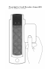
Proximity Card Reader SmartID Ref.
This manual is applicable for the following SmartID products: Partnumber • • • • • • • • • 800-8000 800-8001 800-8015 800-8016 800-8025 800-8030 800-8045 800-8060 800-8075 SmartID/EM4102 SmartID/EM4102/pin SmartID/Hitag1&2 SmartID/Hitag1&2/RW Mifare Serial number Reader/Rs232 ISO14443-3 Mifare Sector reader ISO14443-3 Mifare Sector reader+ pinpad ISO14443-4 DESFire&Mifare rdr (PIV II) ISO14443-4DESFire&MifarePINrdr (PIV II) Extra options for these readers, which are included in this manual, are: • 500-03
Approval If used according to the instructions, this radio system meets the basic requirements of article 3 and the remaining applicable conditions of the R&TTE directive (1999/5/E6) of March 1999.
Table of content: Features............................................................. 5 Indications......................................................... 6 Connections ....................................................... 6 Interface Coding ......... Error! Bookmark not defined. Security.............................................................. 7 Specifications..................................................... 8 Typical read range with an ISO Card ......................8 Power Supply .........
Features The Smart ID Reader has a slim door style mountable design to match any decor. The buried LED’s and buzzer allow the Smart ID Readers to be mounted indoors and outdoors. The Smart ID Reader accepts 4 to 16 Volts DC. The output formats like clock-and-data magstripe (ABA / ISO7811), Wiegand and a number of other formats are determined by the personalization of the card or configuration of the reader.
Mullion mounting The Smart ID Readers can be mounted on a door mullion. Optional there is a mounting kit available in case the small Smart ID reader will be mounted over a wall box (mounting US back box, vertical 84 milimeter (3.31 inch), mounting European back box, horizontal 60 millimeter (2.36 inch)). Indications When a proximity card is decoded successfully the with the card associated code is send to the Host system and the buzzer sounds a short 3KHz beep.
Security Depending on the model and the RF technology used the Smart ID Reader Family offers high security challenge response schemes to protect the RFID air interface against various attacks schemes like record & playback attacks.
Specifications Typical read range with an ISO Card EM4102 up to 7.5 cm (2.95 inch) Hitag1&2 up to 8 cm (3.15 inch) ISO14443 up to 3 cm (1.8 inch) ISO15693 up to 15 cm (5.91 inch) DESFire up to 2 cm (0.79 inch) Power Supply 4 – 16 Volt DC Current requirements Average 248 mA Peak 337 mA Interface Inputs EMC Prot. 10K ohm pull-ups Outputs EMC Prot. open drain 0.5 A/max Dimensions 142 x 46.2 x 25 mm (0.559 x 0.181 x 0.
Certifications EN50022, CE, FCC FCC IDs: • ISO14443: SmartID/ISO14443/SNR/RS232 PX007Z/MFSNR/RS232 > P4E-SMARTPIN-1 • ISO14443-3: SmartID/ISO14443/Sect Classic/ISO14443/Sect > P4E-SMARTPIN-1 • DesFire: SmartID/DesFire Classic/DesFire > P4E-SMARTPIN-1 Consult your National Authority if any authorization is needed for this product. This device complies with Part 15 of the FCC Rules.
SIA recommended cable type for Wiegand signals Cable Length Cable Up to 61m (200.1 ft) Up to 91m (301.8 ft) Up to 153m (502 ft) AWG22 AWG20 AWG18 Diameter inch 0.025 0.03 0.04 Diameter mm 0.64 0.82 1.02 Recommended cable for clock and data ABA track 2 emulation: Up to 25 meter (82 foot), AWG22. Wiegand Signal Levels Voh = Output Voltage idle high Vol = Output Voltage active low Wiegand/Clock&Data ABA reads evaluation The SmartID readers provide true open collector (clean) output C.
Timing 11
Installation instruction 1) Determine an appropriate position for the Reader and drill two holes for mounting the reader to the surface (see mullion mounting drawing on page 12). Do not mount the readers less than 20 cm (7.87 inch) from each other. Make sure that enough room to connect the cable is allowed. Protect the cable against sharp edges and any damage from chaffing. 2) Remove the Terminal Connector 8 pins from the back of the Reader.
5) The Reader should now be secured to the surface using the appropriate screws. Mount the black cover (sticker) and mount the cap over the mounting hole.
Mullion Mounting The size in the drawing is in mm. 1 mm is 0.039 inch.
Connector Assignments Clock/Data (ABA) Green LED 1 input Wiegand Green LED input RS232 RS422 Green LED Green LED input)** input)** Led LED input Led LED input Led LED input)** Led LED input)** Data D1 Do not connect TXA Clock D0 TXD TXA 5 Buzzer input Buzzer input Do not connect RXA 6 Do not Connect Do not Connect RXD RXB Ground Ground Ground Ground Power 4.75 to 15.00 VDC Power 4.75 to 15.00 VDC 2 3 4 7 8 Power Power 4.75 to 4.75 to 15.00 VDC 15.
Optional Tamper Switch 16
Optional Mounting device The sizes in the drawing is in mm. 1 mm is 0.039 inch.
Optional Mounting Plate (Spacer) The sizes in the drawing is in mm. 1 mm is 0.039 inch.
Notes 20
© Copyright 2005 Issue: October 2005 – This manual supercedes and renders invalid all earlier versions. The information in this manual can be changed without prior notice. The information in this manual has been put together to the best of the authors’ knowledge and conscience. The manufacturers accepts no liability for the accuracy or completeness of the information in this manual.