
User Manual


Revision 1.03
1-2 ChannelMaster TX7 Transmitter
1.2 Model Numbering Scheme
Given the model number, a unit's configuration can be determined using the following:
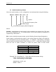
AAAAA – CMTX7 – BB – CCC – YZ
Options
Specified Frequency Plan
Power Output
Model
Generalized Frequency Band Designator
Where:
AAAAA = mean frequency band center in GHz rounded to the closest GHz. This num-
ber is then multiplied by 10. For multiple bands, each center frequency designation is
separated by a backslash "/".
BB = Used to identify the power output, per the following Power Output Designators:
Power Output is represented by Letters for the analog power (as listed in the table be-
low), and Numbers (0-9) for the digital power. For example, a 5W Analog / 2W digital
system would be described with a power indicator of "E2". A Dual-Band system would
have two sets of power indicators, to show the power levels at both bands.
LETTER DESIGNATOR
Analog Power (Watts)
A 1
B 2
C 3
E 5
J 10
L 12
Example: For A Dual Band 2 + 7 GHz radio with these power ratings:
2 GHz: 12 Watt Analog, 5 Watt Digital
7 GHz: 5 Watt Analog, 1.5 Watt Digital
AAAA/AAAA = 20/70, and
BB/BB = L5/E1.5