WARRANTY Intek, Inc.
TABLE OF CONTENTS SECTION 1 ! GENERAL INFORMATION . . . . . . . . . . . . . . . . . . . . . . . . . . . . . . . . . . . . . . . . . 1.1 INTRODUCTION . . . . . . . . . . . . . . . . . . . . . . . . . . . . . . . . . . . . . . . . . . . . . . . . . . . . . 1.2 DESCRIPTION OF OPERATION . . . . . . . . . . . . . . . . . . . . . . . . . . . . . . . . . . . . . . . . 1.3 PRECAUTIONS . . . . . . . . . . . . . . . . . . . . . . . . . . . . . . . . . . . . . . . . . . . . . . . . . . . . . .
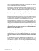
SECTION 1 ! GENERAL INFORMATION 1.1 INTRODUCTION The Model 200 is a “smart” instrument having performance characteristics described in SECTIONS 3, 4, and 6. Rheotherm® precision flow meters are designed to provide accurate linear or non-linear (depending on the model) representation of fluid flow rate. They are manufactured exclusively by Intek, Inc. and employ a patented thermal technique used by industry since 1978.
1.2 DESCRIPTION OF OPERATION Rheotherm flow meters are available with various nonintrusive and intrusive transducer designs, but they all use the same thermal sensing technique. Two temperature sensors are used — one is in thermal equilibrium with the fluid and provides a fluid temperature reference, while the second temperature sensor is located near a heater so that its temperature is slightly above that of the fluid.
Probes (NPT/2I, NPT/I, BF/2I, BF/I, etc.) — Take care not to bend the probes or damage the tips. Do not try to remove or turn the conduit junction box. 3. Check the transducer maximum temperature rating — Do not operate a transducer at or subject it to a temperature above its specified limit. 4. Keep moisture out of the electronic enclosure and sensor junction box. Once cable connections are made in the junction box, make sure the lid is tightly closed. Seal conduit lines if they can become wet inside.
SECTION 2 ! INSTALLATION 2.1 TRANSDUCER !! CAUTION: All transducers have a directional arrow on the tag and/or etched into a metal part. Before installing a sensor, please note proper flow direction. This is critical to sensor operation. !! CAUTION: If you have more than one Rheotherm unit, make sure the complete serial number of the transducer matches the complete serial number of the transmitter. The transducer and transmitter are a matched set.
Some TU transducers have an integrally mounted cable; do not pull on this cable, or attempt to remove the fitting where the cable enters the sensor shell. Fluid temperatures other than ambient require special attention. Thermal gradients from one end of the transducer to the other, as well as along the radius of the connection pipe, are undesirable. Therefore, effective insulation should be installed around the inlet and outlet straight line runs.
2. Intrusive Probes — !! IMPORTANT: Recommended straight run for best accuracy is a minimum 20 diameters up stream and 10 diameters down stream. The various probe transducers are mounted through a threaded collar (NPT/2I and NPT/I) or flanged tee (BF/2I or BF/I). Other fittings and sensor designs are also available and are discussed on the Custom Information page. Generally the probes are sized so the tips extend ½ to 1 inch beyond the pipe center line when properly installed.
The transmitter housing should be installed keeping in mind the length and routing of the transducer cable. Standard cable length is six feet but it can be specified up to 200 feet. If, after calibration of the unit, the cable length is changed (a portion cut off or additional cable spliced on), there may be a shift in the calibration due to the change in cable resistance. The size of this effect depends on the amount of change.
2. Check the analog output configuration of the transmitter and your input device. The analog output terminals for flow and probe temperature are shown in Figure 2 at the far left terminals of JP7. If the instrument is configured for current outputs, set the flow and temperature output type for either passive or active transmitter by positioning the header pin shunts shown in Figure 1 at JP12 and JP13. (Active: Current to loop is sourced by transmitter. Passive: Output receiver sources current.
5. The status output, also located on field wiring terminal, JP7, is a digital 0-15Vdc output. This output will go low in the event of a fault or power loss. If a non-standard option has been ordered there will be additional notes in the SECTION 6.3 — SPECIAL INSTRUCTIONS. 6. The reset input terminals are provided for remote reset of the totalizer. To reset the totalizer these two terminals need to be shorted together.
F ig u r e 3 . S y s t e m I:\O F F IC E \W P M A N U A L \M a n 2 0 0 rv b .
2.4 SERIAL OUTPUT The Model 200 has RS232/422 output receptacles used during factory calibration. There is a data stream that can be accessed with a specially wired six-position RJ-11 jack (modular telephone jack) and computer connection. See Table 1 and Figure 4 for wiring information. If a distance of greater than twenty-five feet is needed for the serial communications, RS-422 should be used instead of RS-232. Inspect the jumper at JP14 (Figure 2) for the proper communication type. TABLE I.
Figure 4 - Serial Communications Interface I:\O F F IC E \W P M A N U A L \M a n 2 0 0 rv b .
SECTION 3 ! OPERATION 3.1 START UP Typically, the instruments come from the factory set up for the flow range of interest to the customer. Following installation all that is required is to switch on power and initiate flow in the measurable flow rate range. Flow sensors that are not calibrated directly on the fluid to be measured are so indicated in this manual (SECTION 6) and require an in-line field calibration. When power is first turned on, the output reading or signal will indicate full scale.
1. Analog Outputs — The unit will have two 0-5Vdc, 0-10Vdc or 4-20 mA signals for flow and temperature outputs. The default configuration for each output is 4-20 mA active transmitter. See SECTION 2.3.3 for a discussion of the output types. The ‘FLOW’ output covers zero to 100% of full scale flow and quickly drops to zero below the instrument’s calibrated low flow value. Refer to the Output Curve (Figure A-1) at the end of the manual.
unplug the RJ-11 serial communication cable to avoid possible signal contention while using the keypad. 1. CHANGING THE DISPLAY VARIABLES Each display line can be independently set for flow, temperature, totalizer, time, date, serial number/calibration/software version or last factory or field calibration adjustment. Use the TOP or BOTTOM LINE SCROLL keys (see Figure 5) to select the desired display variable. Flow = Temp = Temp = Tot = Time Date S/N, Cal Software Ver: Last Cal: 2.
A message of ‘Flow Not Valid’ during calibration means either there is no flow, or flow is out of the measurable range of the unit. !! !! CAUTION: Although the calibration adjustments can be made at any flow value it is recommended that the low and high flows be at least 10% apart from each other. If the desired accuracy is not met with this technique, a factory assisted recalibration may be required.
SECTION 4 ! MAINTENANCE 4.1 GENERAL MAINTENANCE Certain precautions should be taken to insure proper performance of all models of flow instruments. Since the measurement technique involves a signal resulting from heat transfer to the flowing medium, care should be exercised to prevent build-up of varying layers on the walls of the transducer. Layers such as bacterial growth, dried paints, gas bubbles and non-solubles can result in measurement below actual flow rates.
1. The transducer continuity check is performed as follows (see Figure 6-A): A. B. 2. The transducer isolation check is performed as follows (see Figure 6-B): A. B. C. 3. Disconnect the transducer cable from the transmitter. Make resistance measurements between the cable pairs as shown in Figure 6-A. The readings should be as indicated; if not, consult factory for repair. Disconnect the transducer cable from the transmitter. Make the circuit connections illustrated in Figure 6-B.
Figure 6 - Transducer / Electronics Test Configuration I:\O F F IC E \W P M A N U A L \M a n 2 0 0 rv b .
4.5 TROUBLE SHOOTING The following tables provide easy-to-follow instructions to trouble shoot flow indication problems and interpret instrument fault codes. The last table asks for data required by the factory in order to assist you. Be sure to use a high input impedance digital voltmeter for the readings identified in Table IV. All readings are to be taken from terminals BRN through R on JP2 (Figure 2). Complete Table IV and fax it to the factory, (614) 895-0319. TABLE II.
TABLE III. Trouble Shooting Guide - Instrument diagnosed problems OBSERVATION PROBABLE CAUSE ACTION 'GENERAL FAULT' 'MODE 0' 1. Cable cut or not connected at all 'GENERAL FAULT' 'MODE 1' 1. Improper cable hookup 2. Failed A/D circuit. Short between sensor terminals O and BLU of JP2. 3. Damaged flow sensor 1. Verify cable hookup is correct 2. Check cable connections for proper contacts or moisture & corrosion 1. Cable contact corroded 1. Check both ends of cable for moisture or corrosion 2.
Record voltages in Table IV (last column) before contacting the factory. Be sure to use a high input impedance digital voltmeter for the readings identified in Table IV. All readings are to be taken from terminals BRN through R on JP2 (Figure 2) with power on and a typical flow rate flowing through the sensor. Complete Table IV and fax it to the factory (614-895-0319). TABLE IV.
SECTION 5 ! CUSTOMER SERVICE Intek's corporate philosophy is to solve our customer's difficult flow measurement problems. This means that each instrument is custom configured and calibrated for the application. When you purchase a Rheotherm instrument you also receive Intek's outstanding customer service. For sales or product service, call your local representative or Intek directly at (614) 895-0301, 8AM to 5PM EST/EDT weekdays or fax us anytime at (614) 895-0319.
SECTION 6 ! CUSTOM INFORMATION 6.1 UNIT IDENTIFICATION Model no.: Serial no.: Customer identification: 6.2 CONFIGURATION The configuration of this unit, as originally shipped from the factory: Input Power: Q 115 Vac, 50/60 Hz Outputs: Q 230 Vac, 50/60 Hz Q Other Display: 2 x 20 alphanumeric LCD Line Connection: 6.3 SPECIAL INSTRUCTIONS Reference Reference G None G Installation G Calibration adjustment required for start up 3.4.3 G Other I:\O F F IC E \W P M A N U A L \M a n 2 0 0 rv b .
TABLE OF ORIGINAL CALIBRATION DATA FOR FUNCTIONAL TEST Unit Serial Number I TEMP II III IV V )T Flow Output Instrument Display Flow Rate Note: An offset of data in column III (with respect to Column II) may appear if the instrument has been field adjusted. OUTPUT DEFINITION TABLE S/N: CALIBRATION: Output Name Output Range Process Variable (PV) FLOW TEMP PULSE OUT1 * OUT2 * STATUS * * The normal state is 15Vdc as 0Vdc indicates alarm when power is removed.