
User guide


- 9 -
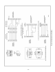
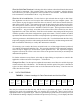
Figure 8. Output Connections and Set-up
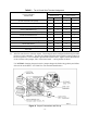
TABLE I. Ten 4-20 mA Wire Terminal Assignment
OUTPUT VARIABLE
DESCRIPTION
CONFIGURATION PIN ASSIGNMENT
Active 4-20 mA Passive 4-20 mA
! + ! +
ACTUAL VOLUME FLOW [ACFM] A B B A
TOTAL MASS FLOW [lbs/hr] C D D C
WATER VAPOR MASS FLOW [lbs/hr] E F F E
RheoVac PRESSURE ["Hg] G H H G
WATER VAPOR SPECIFIC VOLUME [cu. ft/lb] I J J I
WATER to AIR MASS RATIO K L L K
RELATIVE SATURATION [%] M N N M
PARTIAL PRESSURE, WATER ["Hg] O P P O
AIR IN-LEAK [SCFM] Q R R Q
RheoVac TEMPERATURE [°F] S T T S
NOT USED U U U U
Ð RheoVac units have ten 4-20 mA outputs. These outputs can be configured collectively for either
passive or active transmitter. The units are shipped from the factory with the output jumpers in
the active position; i.e. the transmitter provides the current source. Figure 8 shows the locations
of the 4-20 mA select jumper, JP13 of the lower board — active position is shown.
. CAUTION: changing the passive/active jumper changes the field wiring polarity and affects
all ten 4-20 mA channels. See Table I for wire terminal identifications.