Intel® NetStructure™ 1300 Series Storefront Appliance Element Manager User’s Guide
Copyright © 2000 Intel Corporation. All rights reserved. No part of this publication may be reproduced, transmitted, transcribed, stored in a retrieval system, or translated into any language or compute language, in any form or by any means, electronic, mechanical, magnetic, optical, chemical, manual, or otherwise, without the prior written permission of Intel Corporation. Information in this document is provided in connection with the Intel® NetStructure™ 1301, 1305, and 1320 Storefront Appliances.
Contents About the Intel® NetStructure™ 1300 Series Storefront Appliance.......................... 5 Features ............................................................................................................................. 6 Appliance requirements................................................................................................... 8 User profiles ......................................................................................................................
Accessing the appliance interface ............................................................................... 42 Publishing Web pages ................................................................................................... 42 Using FTP .................................................................................................................... 42 Using FrontPage 2000............................................................................................... 44 Adding new users .....
About the Intel® NetStructure™ 1300 Series Storefront Appliance The Intel® NetStructure™ 1300 Series Storefront Appliance is a complete eCommerce hosting platform that combines the proven reliability and unparalleled performance of Intel components, the flexibility of Open Source Internet services software, integrated e-Commerce application and payment cartridge software, and the convenience of remote administration through a Web-based interface.
E-mail service—sites hosted on the appliance also offer customizable Internet messaging services. It's quick and easy to set up mail accounts, aliases, message relaying, message blocking, file transfer limits, message forwarding, and auto-reply, all through the appliance's browser-based interface. Other features—the storefront appliance offers a broad set of features to provide superior performance, reliability, and flexibility.
SSL encryption—enable 128-bit Secure Sockets Layer (SSL) encryption for your hosted domains, as well as SSL encryption for managing the appliance. SNMP support—enable the Simple Network Management Protocol (SNMP) agent on the appliance and configure community access settings. CGI support—enable support on your domains for Common Gateway Interface (CGI) compatible scripts. FrontPage Server Extensions support—enable support on your domains for FrontPage Server Extensions for Web page development.
Extensible software—additional stores can be supported with license key upgrades available from the Intel NetStructure Data Center. The Intel Web site also offers online transactions and downloads of Intel-optimized, third-party software and plug-ins such as payment, content management, logistics, or accounting applications. Spares—upgrade or replace the appliance bezel, hard drive, or complete system. Contact customer support for more information. Accessories—add a front mount or rail accessory kit.
Site administrator (Intershop)—configures e-Commerce services for hosted domains via Intershop's Web-based interface. This e-Commerce site administrator will most likely be the same person as the server administrator noted above. Domain administrator—manages a virtual domain (Web site) located on the appliance. Domain administrators can configure domain settings, manage user accounts, set up mail services, and troubleshoot services for their domains—all from the Web-based interface.
Getting Started Warnings 1. This guide is intended for use by qualified technical personnel with experience in installing and configuring appliances. These appliances are complete, and it is recommended that you not open the appliances unless you are installing an auxiliary hard drive or memory. 2. Read and adhere to all warnings, cautions, and notes in documents supplied with the appliance chassis, power supply, server board, and accessories.
5. Electrostatic discharge (ESD) can damage appliance components. It is strongly suggested that you perform the installation procedures in this guide only at an ESD workstation. If you choose to perform the installation other than at an ESD workstation, you can reduce the risk of ESD by taking these precautions: • Wear an antistatic wrist strap, and attach it to a metal part of the appliance chassis. • Touch the metal on the appliance chassis before touching the server components or connectors.
Checking the power cord Check the power cord to ensure that it's the correct type specifically required in the region where you are installing and/or using the storefront appliance. Do NOT modify or use the supplied AC power cord if it's not the correct type. Power cord and connector requirements include, without limitation, the following: • • • • Rating: Power cords must be rated for available AC voltage and have a current rating at least 125 percent of the current rating of the appliance.
To prepare to rack-mount the appliance 1. Set the appliance near a properly earthed, grounded power outlet: • In the U.S. and Canada—A NEMA 5-15R outlet for 100-120 V • In other geographic areas—A properly earthed, grounded outlet in accordance with the requirements of the local electrical authorities and the electrical code of the region 2.
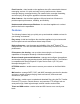
View with the bezel open: B A C D E F G A H A. Rack-mount brackets E. Not applicable for appliances B. LCD F. Hard reset button C. Control buttons G. Not applicable for appliances D. Power button H. COM port 2 Back panel connectors A B C D E F G A. AC input power connector E. Network adapter 2 port B. Not applicable for appliances F. Network adapter 1 port C. Not applicable for appliances G. COM port 1 D.
Booting up and configuring The storefront appliance is a headless e-Commerce appliance that is administered remotely through a Web-based user interface. Before you can access the appliance interface through your browser, you must do the following: • • • • Boot the appliance Assign a static IP address Assign a subnet mask Set the default gateway Error codes If you see a code on the LCD that appears as "XXXX" (a four-digit number) the appliance is generating an error.
To assign a static IP address 1. After booting, the appliance displays the Set IP Address menu with blank octets. Enter an IP address for the appliance by selecting a number for each zero in each octet: 000.000.000.000 x 2. For each zero in each octet, use the up button to change the value from 0 to 1, 2, 3, and so on. All numbers must be entered using three digits. For values less than 100, this will require at least one padding zero.
To set a default gateway 1. After entering the subnet mask, advance to the Set Default Gateway menu. Enter the default gateway by selecting a number for each zero in each octet: 000.000.000.000 x 2. For each zero in each octet, use the up button to change the value from 0 to 1, 2, 3, and so on. You can't set an octet outside the maximum value (255) or the minimum value (000). 3. To move the cursor from one zero to another zero, use the right or left buttons.
Serial cable connection: Pin Signal To Pin DB9-S To Pin (DB25-S) To Pin (RJ45) 1 Data Carrier Detect (DCD) Unused Unused Unused 2 Receive Data (RxD) 3 2 2 3 Transmit Data (TxD) 2 3 5 4 Data Terminal Ready 6 (DTR) 6 6 5 Signal Ground (GND) 5 7 3 or 4 6 Data Set Ready (DSR) 4 20 1 7 Request To Send (RTS) 8 5 Unused 8 Clear To Send (CTS) 7 4 Unused 9 Ring Indicator (RI) Unused Unused Unused 18
Running the First Boot Setup Wizard After the Main menu appears on the LCD, you need to connect to the storefront appliance interface via a Web browser and run the online First Boot Setup Wizard. The setup wizard lets you define your appliance's server name, domain name, DNS settings, date and time settings, and server administrator username and password. In addition, the setup wizard will generate the license key for your online store.
Multi-Server Management Group Operations Group Operations enables the server administrator to make changes, such as setting the date and time, to multiple storefront appliances at the same time. This is done by selecting the appliances from a list and completing tasks located in the left menu. To open the Group Operations pages, click Group Operations in the title bar of the main storefront appliance interface.
Server Management Accessing the appliance interface The storefront appliance can be configured and managed remotely through a Web-based interface, which consists of a series of HTML pages and navigational links. Administrators can use the features found in the interface to create domains and users, monitor system status and resource utilization, configure network services, and perform maintenance and troubleshooting tasks. To access the Web-based interface 1. Open your Web browser.
Administrator login The name that will appear on the Domains page as the name administrator. Password/Confirm The domain administrator password. (Spaces are not permitted.) Domain disk quota Specifies how much disk space this domain is allotted on the appliance. Entering a zero (0) will allocate all the space in the /home directory for this specific domain. Mail support Enables SMTP, POP, and IMAP messaging services for the domain, mail account management, and message relaying.
Changing and removing domains You can change domain settings or delete a domain after it is created. To change a domain 1. In the left menu, click Domains. 2. In the Domain name column, click the domain you want to change. 3. Make any needed changes to the domain settings. For details on each domain option, see “Adding new domains.” To delete a domain 1. In the left menu, click Domains. 2. In the Domain name column, select the checkbox next to the domain(s) you want to delete. 3. Click Delete.
To add a new user 1. In the left menu, click Users. 2. Click Add. 3. On the Add Users page, configure the user account options shown in the following table, then click Add. Option Description Domain Select the domain where the user will reside. Full name The user's full name (example: Terry A. Lee). Login name A login name for the account. Spaces and special characters are not permitted. (example: terry) Password/Confirm The account password. Type the same password in the both fields.
Changing and removing users You can change user account settings or remove a user account after the account is created. However, you cannot remove a user account while that user is logged in. To change a user account 1. In the left menu, click Users. 2. In the Login name column, click the name whose account you want to change. 3. Make any needed changes to the user account. For details on each account option, see “Adding new users.” 4. Click Apply. To delete a user account 1. In the left menu, click Users.
As a server administrator, you can configure these services even if your current login account doesn't permit you to use them. For example, your current login account may not grant you access to send and receive mail on the appliance. But as a server administrator, you can still configure the mail service options by clicking Mail in the left menu. To configure Web service 1. In the left menu, click Web: • To restart the Administrator Web service, click Restart next to Administrator Web.
Enable Realtime Blackhole List (RBL) When selected, this option tries to match the IP address of the e-mail sender against the "Realtime Blackhole List" (RBL). The RBL is a list of all known computers that send junk e-mail. If a match occurs, the e-mail is rejected. This option is not supported behind a restrictive firewall, because the appliance needs to connect to the RBL server. Receive e-mail for hosts/domains (Aliases) The e-mail hosts or domains on this appliance that should receive e-mail.
To configure FTP service 1. In the left menu, click FTP: • To start FTP service, click Start next to FTP. • To stop FTP service, click Stop next to FTP. 2. Configure FTP service settings as explained in the following table, then click Apply. Option Description Allow anonymous login Permits users to log in using FTP without specifying a login name. Banner message for system users A message that appears to all FTP users.
To enable Telnet and SSH service 1. In the left menu, click Telnet/SSH: • To start Telnet or OpenSSH service, click Start. • To stop Telnet or OpenSSH service, click Stop. Configuring e-Commerce services The storefront appliance's e-Commerce service enables domains to host online stores. This capability is comprised of the following three components (that must all be running in order to set up and manage online stores): • • • Application server—processes administration and storefront requests.
Accessing the e-Commerce site administration interface After enabling the e-Commerce service on the appliance, the next step in setting up online stores is to access the e-Commerce site administration interface. This Web-based interface is part of Intershop's Merchant software that comes preinstalled on the appliance. You can configure and manage all storefronts from this interface. To access the e-Commerce site administration interface 1.
Configuring alerts Using e-mail alerting, the appliance can notify you of several events and potential problems.
To configure an alert to notify you when CPU usage has exceeded a threshold 1. In the left menu, click Alerts. 2. Next to CPU, check the E-mail alert check box. 3. In the E-mail alert addresses window, enter the e-mail addresses where you want the alert to be sent if CPU usage exceeds the specified threshold. 4. Click Apply. 5. To configure the CPU usage threshold, click CPU. 6. In the Trending alert thresholds box, set the CPU utilization percent and duration.
To configure an alert to notify you when temperatures have exceeded a threshold 1. In the left menu, click Alerts. 2. Next to Temperatures, check the E-mail alert check box. 3. In the E-mail alert addresses window, enter the e-mail addresses where you want the alert to be sent if temperatures exceed one of the specified thresholds. 4. Click Apply. To configure an alert to notify you when fan speed has crossed a threshold 1. In the left menu, click Alerts. 2. Next to Fans, check the E-mail alert check box.
Publishing Web pages Administrators and end users can author and publish Web content to their respective domains or personal Web sites. First, create your Web pages locally using any HTML authoring tool, and then transfer the files to the appropriate subdirectory on the appliance.
Directory paths for site users For site users, files are transferred to your personal directory by default. The directory path is: /home/domain//users//web where is the fully qualified domain name, and is your login name.
Rebooting and shutting down If you're experiencing consistent problems with a particular Web service, rebooting the appliance may solve the problem. The reboot process can take several minutes to complete. To reboot the appliance 1. Click Reboot/Shutdown. 2. Click Reboot > Yes. The shut-down process can take several minutes to complete. To shut down the appliance 1. Click Reboot/Shutdown. 2. Click Shutdown > Yes. You can also reboot and shutdown the appliance at its front panel console.
Control keys Use these keys to navigate and select options from the menu system displayed on the LCD. The top and bottom arrow keys move through the listed menus and options. The right arrow key selects the highlighted option. The left arrow key returns you to the previous menu.
Main menu The Main menu is the access point for all of the features available through the front panel console. To view the Main menu, hold down any of the arrow keys for three seconds.
To reset the root password 1. From the Defaults menu, select Root password.... 2. To restore the default root user password, select Default. 3. Or, to generate a new, unique six-character password, select Random. Continue selecting Random until you find a password you like. Once you have that password, press the right arrow key. You may want to write down the password and keep it in a secure place. To restore the password files Important: Only perform this operation in extreme situations.
Network menu The Network menu enables you to view and configure network addressing for your appliance's network adapters, subnet mask, and default gateway. If necessary, you can change the IP address for a network adapter. To change or view the IP address network devices • • Select Configure..., and then select the network device you want to configure. Use the arrow keys to enter the new IP address. Select Status..., and then select the network device you want to view.
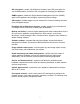
LED indicators The following illustration and table describes the nine LEDs located on the front panel (as viewed with the bezel closed): A B C D E F G H I J A LED Description B. Power On (green) Indicates if the appliance is in a powered-on state. A blinking green light indicates that a system message is waiting or the appliance is in sleep mode. C. System Sleep/Fault (amber) Indicates the appliance has detected a fault or is in sleep mode. A blinking amber light indicates a system failure.
Domain Management Accessing the appliance interface The storefront appliance can be configured and managed remotely through a Web-based interface, which consists of a series of HTML pages and navigational links. Administrators can use the features found in the interface to create domains and users, monitor system status and resource utilization, configure network services, and perform maintenance and troubleshooting tasks. To access the Web-based interface 1. Open your Web browser.
To publish using FTP 1. Start your FTP application and establish a session with the storefront appliance. 2. Transfer your files to your personal directory. Refer to the manufacturer's documentation for questions regarding your FTP client application.
Using FrontPage 2000 If FrontPage Server Extensions have been enabled for a hosted domain, the primary domain administrator can publish Webs directly from FrontPage (secondary domain administrators and other end users cannot publish directly from FrontPage). To publish using FrontPage 2000 1. 2. 3. 4. 5. Open your FrontPage Web. Click File | Publish Web. Enter the IP address or domain name after the http://. Click Publish.
To add a new user 1. In the left menu, click Users. 2. Click Add. 3. On the Add Users page, configure the user account options shown in the following table, then click Add. Option Description Domain Select the domain where the user will reside. Full name The user's full name (example: Terry A. Lee). Login name A login name for the account. Spaces and special characters are not permitted. (example: terry) Password/Confirm The account password. Type the same password in the both fields.
Changing and removing users You can change user account settings or remove a user account after the account is created. However, you cannot remove a user account while that user is logged in. To change a user account 1. In the left menu, click Users. 2. In the Login name column, click the name whose account you want to change. 3. Make any needed changes to the user account. For details on each account option, see “Adding new users.” 4. Click Apply. To delete a user account 1. In the left menu, click Users.
SSI support Enables support of Server Side Includes (SSI) such as current date, and so on. CGI support Adds support for Common Gateway Interface (CGI) compatible scripts, enabling interactive/dynamic Web content. Configure SSL Configure Secure Sockets Layer (SSL) to enable encryption support for your domains. Virtual FTP support Enables users to upload and download files on the appliance using the File Transfer Protocol (FTP) service.
Domain directory structure When a domain is added, the following directory is created: /home/domain/domain[n] where [n] is an integer starting with 1. This directory is owned by the domain administrator. To simplify correlation between a domain's real name and domain[n], a soft link matching the domain's FQDN is linked to the /home/domain/domain[n] directory. This provides the administrator with easier access to the domain, and is not required for system operation.
Hardware Configuration and Management Removing and replacing the cover To remove the cover 1. Use a Phillips screwdriver to remove the screw from the front edge of the cover. 2. Grasp the back edge of the cover and simultaneously pull from the back edge and push near the front until the cover slides out from under the edge of the server front panel. 3. Grasp the notch in the front center of the cover and lift to remove the cover. To replace the cover 1.
Adding memory Make sure that the DIMM board you want to install has the appropriate characteristics. Caution DIMM board edge connectors are keyed and can be inserted only one way. Applying too much pressure or misaligning the board in the socket can damage the sockets or DIMM board edge connectors. Reduce the risk of damaging a connector by installing the DIMM boards starting with the back socket on the server board and moving toward the front of the server.
Adding a second hard drive Adding a second hard drive lets you expand the file storage capacity of your appliance or provide disk redundancy to ensure complete recovery of domain, user, and configuration files in case of a disk failure. After you add a second hard drive to your appliance, use the Web-based interface to configure how it will be used by extending the /home directory or mirroring the first hard drive.
To install the hard drive in the mounting bracket This procedure assumes that the mounting bracket has been removed from the drives. 1. Place the drive in the mounting bracket with the component side down and the front of the drive facing the front (tabbed) end of the mounting bracket. 2. Align the four mounting-bracket screw holes with the mating holes (two on each side) in the drive housing. 3. Use a Phillips screwdriver and four screws to securely attach the mounting bracket to the drive.
Configuring the hard drive Once you have installed a new hard drive, you can configure it through the appliance's Web interface. Configuration options include: • • Extending the /home directory Mirroring the disk Regardless of how you will configure it, make sure the new drive is: • • The same type of drive as the original hard drive. The storefront appliance uses a SCSI drive. The same size or larger as the original drive.
Mirroring the disk To mirror the disk 1. Install the hard drive. 2. At the Status page of the interface, click the more... link next to Drive space usage. The Second drive status field at the bottom of the page will show the current status of the newly installed drive. 3. Click Disk mirroring. This process runs in the background. A percentage bar will show the progress of the mirroring. (For a full IDE drive, mirroring can take up to 120 minutes to complete. For a full SCSI drive, it takes 1015 minutes.) 4.
Troubleshooting and Support Troubleshooting This section provides possible solutions for these specific problems. Try the solutions in the order given. If the problem persists, contact technical support or an authorized dealer for help. Power indicator does not light Check the following: • • Is the appliance operating normally? If so, the power LED is probably defective or the cable from the front panel to the server board is loose.
Hard disk drive activity indicator does not light If you've installed one or more hard disk drives in your appliance, check the following: • • • • Are the power and signal cables to the drive properly installed? Are all relevant switches and jumpers on the hard drive and adapter board set correctly? Is the onboard IDE or SCSI controller enabled? Is the hard disk drive properly configured? Hard disk drive activity The hard disk drive activity light on the front panel lights when either an IDE hard disk dri
Link LED does not light Check the following: • • • • Make sure you've loaded the network drivers. Check all cable connections. Make sure the network cable is connected to the port marked "Adapter 1" on the back of the appliance. Make sure you have the correct type of cable between the adapter and the hub. Some hubs require a crossover cable while others require a straight through cable (for more information on crossover cabling, see your hub documentation).
Accessing the emergency partition The appliance has an emergency partition containing backup that can be used for rebooting and reconstruction under emergency conditions. In addition to software and operating system files, this partition contains: • • • A daily copy of the network configuration. Password information for the root user and serveradmin users. A complete daily backup copy of the files containing the account and password information. These files are stored as \etc\passwd.full and \etc\shadow.
Intel e-Business Data Center Store http://www.intel.com/netstructure/store FTP download site ftp://download.intel.com Printing the product documentation If you have specific support questions regarding the Intel NetStructure 1300 Series Storefront Appliance, you can often find the information you need in the product documentation. Check the documentation before contacting the technical support staff. You can find the Intel® NetStructure™ 1300 Storefront Appliance User's Guide (in printable .
Facilitating your support call In order to speed up the resolution of your support inquiry, be prepared to give the following information: • • • • • • Serial number of the appliance (to find the serial number from the appliance interface, click more hardware information... at the bottom of the Status page). Any error messages you have received, including the time when the error occurred.
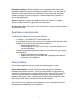
Appendices Appliance specifications Physical description The diagram below shows the location of the major system components in your appliance: G H E D C B I J A F A. Hard drive F. Fan 1 B. Additional hard drive bracket G. Fan 2 C. DIMM sockets H. Fan 3 D. Power supply I. Fan 4 E. Server board J.
The following table lists the physical dimensions and required clearances for the appliance: Height 4.32 cm (1.70 inches) Width 42.55 cm (16.75 inches) Depth 60.96 cm (24 inches) Required front clearance 30.48 cm (12 inches) with inlet airflow 35°C/95°F or less Required rear clearance 21.60 cm (9 inches) with no airflow restriction Operating temperatures The operating temperature of the appliance, when installed in a rack, must not go below 5 °C (41 °F) or above 35 °C (95 F).
Hardware components The following table lists the default hardware components for the storefront appliance: Component Description Processor 750 MHz Intel® Pentium® III processor Memory 512 MB (1 store 1301 model) 512 MB (5 store 1305 model) 1 GB (20 store 1320 model) Hard drive single 9 GB SCSI Adaptec 2940 LP drive (expandable to dual 9 GB drives in mirrored or extended volume configuration) Network adapter dual Intel Pro 10/100+ Ethernet cards SCSI adapter Adaptec 2940 UW Slimline* Power suppl
Installed software The following table lists the pre-installed software and versions that ship with the storefront appliance: Software Description OS Linux* kernel 2.2.16.3 Linux distribution based on Red Hat Linux* distribution 6.2 Web server Apache 1.3.12 Mail server Sendmail* 8.
Serial cable connection Pin Signal To Pin (DB9-S) To Pin To Pin (DB25-S) (RJ45) 1 Data Carrier Detect (DCD) (Unused) -- -- 2 Receive Data (RxD) 3 2 2 3 Transmit Data (TxD) 2 3 5 4 Data Terminal Ready 6 (DTR) 6 6 5 Signal Ground (GND) 5 7 3 or 4 6 Data Set Ready (DSR) 4 20 1 7 Request To Send (RTS) 8 5 -- 8 Clear To Send (CTS) 7 4 -- 9 Ring Indicator (RI) -- -- (Unused) Rack-mount precautions Familiarize yourself with the following precautions before rack-mounting
Overcurrent protection—The appliance is designed for an AC line voltage source with up to 20 amperes of overcurrent protection. If the power system for the equipment rack is installed on a branch circuit with more than 20 amperes of protection, you must provide supplemental protection for the appliance. If more than one appliance is installed in the rack, the power source for each appliance must be from a separate branch circuit.
0111h Floppy A: Error 0112h Floppy B: Error 0113h Hard Disk 0 Error 0114h Hard Disk 1 Error 0115h Hard Disk 2 Error 0116h Hard Disk 3 Error 0117h CD-ROM Disk 0 Error 0118h CD-ROM Disk 1 Error 0119h CD-ROM Disk 2 Error 011Ah CD-ROM Disk 3 Error 011Bh Date/Time Not Set 011Eh Cache Memory Bad 0140h PCI Error 0141h PCI Memory Allocation Error 0142h PCI IO Allocation Error 0143h PCI IRQ Allocation Error! 0144h Shadow of PCI ROM Failed 0145h PCI ROM Not Found, May be OK For This
8190h Watch Dog Failed on Last Boot 8191h 2:1 Core to Bus Ratio: Processor Cache disabled 8192h L2 Cache Size Mismatch 8193h CPUID, Processor Stepping Are Different 8194h CPUID, Processor Family Are Different 8195h Front Side Bus Speed Mismatch.
Temperature conversion chart Because temperature-monitoring computer hardware reports the temperature in degrees Celsius, users in the United States may want to convert temperatures to Fahrenheit. The table below lists the Fahrenheit equivalents to their Celsius values: ºC ºF ºC 0º 32.0º 1º ºF ºC ºF ºC ºF 26º 78.8º 51º 123.8º 76º 168.8º 33.8º 27º 80.6º 52º 125.6º 77º 170.6º 2º 35.6º 28º 82.4º 53º 127.4º 78º 172.4º 3º 37.4º 29º 84.2º 54º 129.2º 79º 174.2º 4º 39.2º 30º 86.
Supported memory The BIOS assesses the SDRAM size and speed using the serial presence detect (SPD) data structure programmed into an EEPROM on the DIMM. Memory size is 16 MB to 1 GB. DIMM board memory size can be mixed but must be either all unbuffered or all registered. Slot vacancies are allowed.
Supported memory characteristics DIMM Configuration DRAM DRAM DRAM Singlesize technology depth width sided DIMM (size x 64 bit) 16 MB 2 Mbit x 72 16 Mbit 2 Mbit 8 bit 32 MB 4 Mbit x 72 16 Mbit 2 Mbit 8 bit 32 MB 4 Mbit x 72 16 Mbit 4 Mbit 4 bit 64 MB 8 Mbit x 72 16 Mbit 4 Mbit 4 bit 32 MB 4 Mbit x 72 64 Mbit 4 Mbit 16 bit 64 MB 8 Mbit x 72 64 Mbit 4 Mbit 16 bit 64 MB 8 Mbit x 72 64 Mbit 8 Mbit 8 bit 128 MB 16 Mbit x 72 64 Mbit 8 Mbit 8 bit 128 MB 16 Mbit x 72 64 Mbit 16 M
Log files When a current log file reaches its maximum size, it is compressed, renamed, and stored in rotation. The first rotation is renamed with the numeral 1 (example: /var/log/maillog becomes /var/log/maillog1). Each time the current log file becomes full, the backup files are rotated to the next sequential number. When the maximum number of rotating backup log files exists, the next rotation clears the oldest log file (/var/log/maillog5) to make room for newer entries.
Changes to Red Hat Linux distribution 6.2 The Linux version installed on the appliance is based on a "Server" installation of Red Hat Linux 6.2. The Red Hat installer defines several groups of RPMs (RPM Package Manager) that may be installed when a "Server" installation is selected.
Regulatory and Environmental Specifications Declaration of the Manufacturer or Importer We hereby certify that this product is in compliance with European Union EMC Directive 89/336/EEC, using standards EN55022 (Class A) and EN55024 and Low Voltage Directive 73/23/EEC, standard EN60950. Safety Compliance USA: UL 1950 – 3rd Edition/CSA 22.2. No. 950-M93 Canada: UL certified – 3rd Edition/CSA 22.2. No. 950-M93 for Canada (product bears the single UL mark for U.S.
Electromagnetic Compatibility (EMC) USA: FCC CFR 47 Part 2 and 15, Verified Class A Limit Canada: IC ICES-003 Class A Limit Europe: EMC Directive, 89/336/EEC EN55022, Class A Limit, Radiated & Conducted Emissions EN55024 ITE Specific Immunity Standard EN61000-4-2 ESD Immunity (Level 2 Contact Discharge, Level 3 Air Discharge) EN61000-4-3 Radiated Immunity (Level 2) EN61000-4-4 Electrical Fast Transient (Level 2) EN61000-4-5 AC Surge EN61000-4-6 Conducted RF EN61000-4-11 Voltage Dips and Interrupts EN61
Any changes or modifications not expressly approved by the grantee of this device could void the user’s authority to operate the equipment. The customer is responsible for ensuring compliance of the modified product. Only peripherals (computer input/output devices, terminals, printers, etc.) that comply with FCC Class A limits may be attached to this computer product. Operation with non-compliant peripherals is likely to result in interference to radio and TV reception.
ICES-003 (Canada) Cet appareil numérique respecte les limites bruits radioélectriques applicables aux appareils numériques de Classe A prescrites dans la norme sur le matériel brouilleur: “Appareils Numériques”, NMB-003 édictée par le Ministre Canadian des Communications.