
Guide


LGA775 Socket Heatsink Loading
Thermal and Mechanical Design Guidelines 73
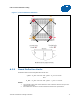
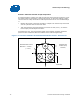
Figure 7-7. Example—Defining Heatsink Preload Meeting Board Deflection Limit
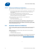
A.3.4 Additional Considerations
Intel recommends to design to {d_BOL - d_ref = 0.15 mm} at BOL when EOL
conditions are not known or difficult to assess
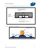
The following information is given for illustration only. It is based on the reference
keep-out, assuming there is no fixture that changes board stiffness:
d_ref is expected to be 0.18 mm on average, and be as high as 0.22 mm
As a result, the board should be able to deflect 0.37 mm minimum at BOL
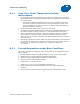
Additional deflection as high as 0.09 mm may be necessary to account for additional
creep effects impacting the board/clip/fastener assembly. As a result, designs could
see as much as 0.50 mm total downward board deflection under the socket.
In addition to board deflection, other elements need to be considered to define the
space needed for the downward board total displacement under load, like the potential
interference of through-hole mount component pin tails of the board with a
mechanical fixture on the back of the board.
NOTES:
1. The heatsink preload must remain below the maximum load limit of the package at all
times (Refer to processor datasheet).
2. Board deflection should not exceed motherboard manufacturer specifications.