21152 PCI-to-PCI Bridge Evaluation Board User’s Guide July 1998 Order Number: 278127-001
Information in this document is provided in connection with Intel products. No license, express or implied, by estoppel or otherwise, to any intellectual property rights is granted by this document.
Contents 1 Introduction......................................................................................................................... 1 1.1 1.2 1.3 1.4 1.5 1.6 2 Overview ............................................................................................................... 1 Features ................................................................................................................ 1 Major Components ........................................................................
Figures 1-1 1-2 1-3 1-4 1-5 1-6 4-1 EB152 Major Components .................................................................................... 2 Secondary PCI Slot Numbering ............................................................................ 3 EB152 with One Secondary Bus Option Card ...................................................... 4 EB152 with Two Secondary Bus Option Cards.................................................... 4 Tri-Level with Two EB152s .....................................
Introduction 1 This document describes the Intel 21152 PCI-to-PCI Bridge Evaluation Board (also referred to as the EB152). The EB152 is an evaluation and development board for systems based on the Intel 21152 PCI-to-PCI Bridge chip (the 21152). Intel’s 21152 is a second-generation PCI-to-PCI bridge and is fully compliant with the electrical and protocol requirements of the PCI-to-PCI Bridge Architecture Specification, Revision 2.1, and the PCI-to-PCI Bridge Architecture Specification, Revision 1.0.
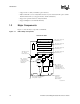
Introduction • Supports four secondary 5 V PCI bus option card slots. • May be built with 3.3-V secondary PCI card slots. If you are interested in this option, call the Intel Information Line (see, Support, Products, and Documentation). • Supports an optional external secondary bus arbiter. • Supports multiple levels of PCI bus hierarchy 1.3 Major Components Figure 1-1 shows the major components on the EB152. Figure 1-1.
Introduction 1.4 Jumpers The EB152 provides 10 jumpers that can be used for debugging and for special evaluation tests. The jumpers can be used for monitoring CLK signals and 21152 secondary PCI signals. Additional optional jumpers control secondary bus arbitration. Table 1-1 shows the connections required to allow observation of these signals at scope pod connector pins. Table 1-1.
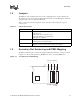
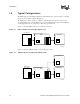
Introduction 1.6 Typical Configurations The EB152 supports various PCI configurations with different types of devices. Figure 1-3 through Figure 1-6 show examples of PCI configurations. The primary bus connector attaches to a PCI slot on the motherboard of the host system or to a secondary PCI bus slot on another EB152. A 5-V or universal PCI option card, or another EB152, can be plugged into any one of the four secondary bus option card slots.
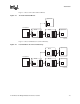
Introduction Figure 1-5 shows a tri-level bus with two EB152s. Figure 1-5. Tri-Level with Two EB152s Option Card PCI Device Host System Motherboard EB152 21152 EB152 21152 Option Card PCI Device LJ-05031.AI4 Figure 1-6 shows four PCI buses in a tri-level hierarchy. Figure 1-6. Four PCI Buses in a Tri-Level Hierarchy EB152 21152 Option Card PCI Device Host System Motherboard EB152 21152 EB152 21152 Option Card PCI Device LJ-05032.
Installation 2 This chapter provides information about the EB152 specifications and the hardware and software requirements for using the EB152. It also describes how to install the EB152. 2.1 Specifications The physical and power specifications for the EB152 are as follows: Dimensions: Height: 20.0 cm (7.90 in) Width: 13.2 cm (5.20 in) Power Requirements: dc amps @ 5 V: 2.0 A (maximum) 2.
Installation 2.4 Installation Procedure Figure 1-1 illustrates the EB152 and shows the location of components referred to in this section. Install the EB152 as follows: 1. Power down the host system that will contain the EB152. 2. Place the motherboard with the associated support devices on a bench if mechanical constraints do not allow testing of the EB152 and the expansion slots inside the system box. 3. Configure your system as follows: a. Insert the card edge of the EB152 into a PCI slot. b.
3 Interrupt Routing This chapter describes the way in which interrupts are routed. This information is provided as a reference for designers. Because a total of 16 interrupts are connected to the secondary bus PCI slots (INTA#, INTB#, INTC#, and INTD# for each slot) and only four interrupts are driven to the card edge, the 16 incoming interrupts must be combined. This ORing of interrupts is performed in accordance with the PCI-to-PCI Bridge Architecture Specification.
Interrupt Routing Table 3-2 lists the interrupts from the devices on the secondary slots to the interrupts on the EB152 fingers. Table 3-2.
Secondary Bus Arbitration 4 This chapter describes the use of jumpers to test 21152 secondary bus arbitration, an optional programmable feature. For more detailed information about the 21152 arbiter, refer to the 21152 PCI-to-PCI Bridge Data Sheet.
Secondary Bus Arbitration Figure 4-1. Arbitration Jumpers Viewed from Side 1 J6 J3 J13 J5 J4 J2 J11 J9 J10 J8 J12 W7 J7 E3 _ Socket for Optional PAL to Control Secondary Bus External Arbitration W5 J1 E3 W4 E4 W1 21152 W1, W4, J7 _ Secondary Bus External/Internal Arbitration Configurable Jumpers LJ-05127.AI4 Table 4-1 describes the operation of internal arbitration jumpers. Table 4-1.
Secondary Bus Arbitration Table 4-2 describes the operation of jumpers for external arbitration with PAL. Table 4-2. External PAL Arbitration Jumper Positions Jumper Position Description J7 Top Selects the PAL as the source of secondary grants. W4 Right Selects the board signal gt_out<4> (the external secondary grant to the 21152) to drive the 21152 s_req_l<0> input.
Kit Contents A This appendix lists the contents of the Intel Semiconductor 21152 PCI-to-PCI Bridge Evaluation Kit.
Support, Products, and Documentation If you need technical support, a Product Catalog, or help deciding which documentation best meets your needs, visit the Intel World Wide Web Internet site: http://www.intel.com Copies of documents that have an ordering number and are referenced in this document, or other Intel literature may be obtained by calling 1-800-332-2717 or by visiting Intel’s website for developers at: http://developer.intel.