
Computer Hardware User Manual


21152 PCI-to-PCI Bridge Evaluation Board
User’s Guide 1-3
Introduction
1.4 Jumpers
The EB152 provides 10 jumpers that can be used for debugging and for special evaluation tests.
The jumpers can be used for monitoring CLK signals and 21152 secondary PCI signals. Additional
optional jumpers control secondary bus arbitration.
Table 1-1 shows the connections required to allow observation of these signals at scope pod
connector pins.
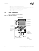
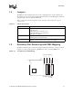
1.5 Secondary Slot Numbering and IDSEL Mapping
The PCI secondary bus option card slots are mapped to PCI device numbers 4, 5, 6, and 7 as shown
in Figure 1-2. The secondary bus lines s_ad<20:23> are used as secondary IDSEL lines.
Table 1-1. Jumper Connections
Jumper Description
J1 This jumper monitors the following signals:
p_clk (PCI clock)
s_clk_o<4:1> (four secondary PCI clocks)
s_clk_o<0> (fed back to the s_clk input pin)
s_gnt_l<2> and s_gnt_l<3>.
J2, J8 through J12 Logic analyzer pods can be plugged into these jumpers for
monitoring 21152 secondary PCI signals.
W1, W4, J7 These jumpers control secondary bus arbitration. Chapter 4, Secondary Bus
Arbitration, provides information about configuring these jumpers.
Figure 1-2. Secondary PCI Slot Numbering
LJ-04468.AI4
456
PCI Device Numbers
PCI Option Card Slots
7