SSI ERP2U (Entry Redundant Power 2U) Power Supply Design Guide A Server System Infrastructure (SSI) Specification For 2U Rack Chassis Power Supplies Version 1.
SSI ERP2U Power Supply Design Guide, V1.0 Disclaimer: THIS SPECIFICATION IS PROVIDED "AS IS" WITH NO WARRANTIES WHATSOEVER, INCLUDING ANY WARRANTY OF MERCHANTABILITY, NONINFRINGEMENT, FITNESS FOR ANY PARTICULAR PURPOSE, OR ANY WARRANTY OTHERWISE ARISING OUT OF ANY PROPOSAL, SPECIFICATION OR SAMPLE. WITHOUT LIMITATION, THE PROMOTERS (Intel Corporation, NEC Corporation, Dell Computer Corporation, Data General a division of EMC Corporation, Compaq Computer Corporation, Silicon Graphics Inc.
SSI ERP2U Power Supply Design Guide, V1.0 Contents 1 Purpose ..............................................................................................................................................5 2 Conceptual Overview..........................................................................................................................5 3 Definitions/Terms/Acronyms..............................................................................................................
SSI ERP2U Power Supply Design Guide, V1.0 8.2 PWOK (Power OK).......................................................................................................................... 27 8.3 SMBus Communication.................................................................................................................... 28 8.3.1 Field Replacement Unit (FRU) Signals ....................................................................................... 28 8.3.2 Module FRU Data..........................
SSI ERP2U Power Supply Design Guide, V1.0 1 Purpose This 2U Rack Power Supply Design Guide defines a common redundant power sub-system used in 2U rack mount servers. The power sub-system is made up of a cage and hot swap redundant power modules. This Design Guide covers the mechanical and electrical requirements of this power sub-system. The requirements of the individual hot swap modules are left open. This power sub-system may range from 350 to 600 watts and is used in a hot swap redundant configuration.
SSI ERP2U Power Supply Design Guide, V1.0 3 Definitions/Terms/Acronyms Required The status given to items within this design guide, which are required to meet SSI guidelines and a large majority of system applications. Recommended The status given to items within this design guide which are not required to meet SSI guidelines, however, are required by many system applications.
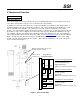
SSI ERP2U Power Supply Design Guide, V1.0 4 Mechanical Overview STATUS Required (Optional) Note: Some features are noted as optional in the enclosure drawing figure below. These features may be use in some chassis designs where only top access is allowed for the cage mounting. The ERP2U is a power sub-system made up of a cage and redundant, hot swappable power supply modules. A mechanical drawing of the cage is shown below in Figure 1.
SSI ERP2U Power Supply Design Guide, V1.0 4.1 Optional Chassis Mounting Features STATUS Optional The optional top access mounting method fastens to the system chassis via three mounting holes; two on the exterior face and one with the tab on the interior face of the cage. There are also four rectangular cutouts on the bottom of the cage. These are intended to drop over the top of rectangular features in the bottom of the chassis. This will help position the cage and secure it laterally.
SSI ERP2U Power Supply Design Guide, V1.0 4.2.1 Redundant Cooling STATUS Recommended It is recommended that the power supply cooling be redundant. This means the cooling device is located in the hot swap power supply modules or there are redundant devices located on the cage. 4.3 Temperature Requirements STATUS Recommended The power supply shall operate within all specified limits over the Top temperature range.
SSI ERP2U Power Supply Design Guide, V1.0 power supplies shall continue to operate with no interruption of performance. It is required that all redundant power supply modules be present to support redundant AC inlets. 5.3 AC Input Voltage Specification STATUS Required The power supply must operate within all specified limits over the following input voltage range. Harmonic distortion of up to 10% THD must not cause the power supply to go out of specified limits.
SSI ERP2U Power Supply Design Guide, V1.0 5.5 AC Line Dropout STATUS Required An AC line dropout is defined to be when the AC input drops to 0 VAC at any phase of the AC line for any length of time. During an AC dropout of one cycle or less the power supply must meet dynamic voltage regulation requirements over the rated load. An AC line dropout of one cycle or less shall not cause any tripping of control signals or protection circuits.
SSI ERP2U Power Supply Design Guide, V1.0 5.8 AC Line Transient Specification STATUS Recommended AC line transient conditions shall be defined as “sag” and “surge” conditions. Sag conditions (also referred to as “brownout” conditions) will be defined as the AC line voltage dropping below nominal voltage. Surge conditions will be defined as the AC line voltage rising above nominal voltage. The power supply shall meet the requirements under the following AC line sag and surge conditions.
SSI ERP2U Power Supply Design Guide, V1.0 6 DC Output Specification These are the output requirements for the power supply assembly including cage and module. 6.1 Output Connectors The power supply assembly shall have the following output connectors and wire harness configuration. 6.1.1 Required Baseboard power connector Connector housing: 24-Pin Molex 39-01-2240 or equivalent Contact: Molex 44476-1111 or equivalent Table 6: P1 Baseboard Power Connector 6.1.
SSI ERP2U Power Supply Design Guide, V1.0 6.1.3 Required Peripheral Power Connectors Connector housing: Amp 1-480424-0 or equivalent Contact: Amp 61314-1 contact or equivalent Table 8: Peripheral Power Connectors Pin Signal 18 AWG Color 1 +12V2 (or +12V3) Yellow 2 COM Black 3 COM Black 4 +5 VDC Red Note: The +12V power to peripherals may be split between 2 or 3 channel for the purpose of limiting power to less than 240VA. 6.1.
SSI ERP2U Power Supply Design Guide, V1.0 6.1.5 Optional Server Signal Connector Connector housing: 5-pin Molex 50-57-9405 or equivalent Contacts: Molex 16-02-0088 or equivalent (gold plated) Notes: It is recommended to use gold plated signal contacts on both the power supply connector and the baseboard header. If the optional server signal connector is not used on the power supply the 3.3VRS and ReturnS lines shall be crimped into the contacts in the baseboard power connector.
SSI ERP2U Power Supply Design Guide, V1.0 6.4 Output Power/Currents STATUS Recommended The following tables define the power and current ratings for two recommend power levels. Depending upon the system design, the power supply modules may have only three outputs (+12V, -12V, and 5VSB) or the full five outputs (+3.3V, +5V, +12V, -12V, and 5VSB). If only three outputs are provided from the module, the cage shall have additional DC/DC converters to generate +5V and +3.
SSI ERP2U Power Supply Design Guide, V1.0 6.4.1 Standby Outputs STATUS Required The 5 VSB output shall be present when an AC input greater than the power supply turn on voltage is applied. 6.5 Voltage Regulation STATUS Required The power assembly output voltages must stay within the following voltage limits when operating at steady state and dynamic loading conditions. These limits include the peak-peak ripple/noise specified in Section 5.9.
SSI ERP2U Power Supply Design Guide, V1.0 6.6 Dynamic Loading STATUS Required The output voltages shall remain within the limits specified in Table 13 for the step loading and within the limits specified in Table 15 for the capacitive loading. The load transient repetition rate shall be tested between 50 Hz and 5 kHz at duty cycles ranging from 10%-90%. The load transient repetition rate is only a test specification.
SSI ERP2U Power Supply Design Guide, V1.0 Table 17: Ripple and Noise 6.9 +3.3 V +5 V +12 V -12 V +5 VSB 50 mVp-p 50 mVp-p 120 mVp-p 120 mVp-p 50 mVp-p Redundancy The power sub-system may have different levels of redundancy depending upon the availability requirements of the system. The Required, Recommended, and Optional items are broken down here. To be redundant each item must be in the hot swap power supply module.
SSI ERP2U Power Supply Design Guide, V1.0 DC connect at the same time as the module is inserted into the cage. No damage to the connector contacts shall occur. The module may power on or come up into standby mode. Many variations of the above are possible. Supplies need to be compatible with these different variations depending upon the sub-system construction.
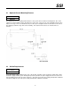
SSI ERP2U Power Supply Design Guide, V1.0 6.11 Timing Requirements STATUS Required These are the timing requirements for the power assembly operation. The output voltages must rise from 10% to within regulation limits (Tvout_rise) within 5 to 200ms. The +3.3 V, +5 V and +12 V output voltages should start to rise at about the same time. All outputs must rise monotonically. The +5 V output needs to be greater than the +3.3 V output during any point of the voltage rise.
SSI ERP2U Power Supply Design Guide, V1.0 Table 19: Turn On/Off Timing Item Description MAX UNITS Tsb_on_delay Delay from AC being applied to 5 VSB being within regulation. MIN 1500 ms T ac_on_delay Delay from AC being applied to all output voltages being within regulation. 2500 ms Tvout_holdup Time all output voltages stay within regulation after loss of AC. 18 ms Tpwok_holdup Delay from loss of AC to deassertion of PWOK.
SSI ERP2U Power Supply Design Guide, V1.
SSI ERP2U Power Supply Design Guide, V1.0 7 Protection Circuits STATUS Required Protection circuits inside the power supply shall cause only the power supply’s main outputs to shutdown. If the # power supply latches off due to a protection circuit tripping, an AC cycle OFF for 15 s and a PSON cycle HIGH for 1 s must be able to reset the power supply. 7.1 Current Limit STATUS Required The power supply shall have current limit to prevent the +3.
SSI ERP2U Power Supply Design Guide, V1.0 Table 21: Over Current Protection Voltage 7.3 Over Current Limit (Iout limit) +3.3 V 110% minimum; 150% maximum +5 V 110% minimum; 150% maximum +12V1,2,3 Peak current minimum; 20A maximum Over Voltage Protection STATUS Required The power supply over voltage protection shall be locally sensed in the hot swap modules. The power supply shall shutdown and latch off after an over voltage condition occurs.
SSI ERP2U Power Supply Design Guide, V1.0 8 Control and Indicator Functions The following sections define the input and output signals from the power supply. Signals that can be defined as low true use the following convention: # signal = low true 8.1 PSON# STATUS Required # # The PSON signal is required to remotely turn on/off the power supply. PSON is an active low signal that turns on the +3.3 V, +5 V, +12 V, and -12 V power rails.
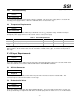
SSI ERP2U Power Supply Design Guide, V1.0 8.2 PWOK (Power OK) STATUS Required PWOK is a power OK signal and will be pulled HIGH by the power supply to indicate that all the outputs are within the regulation limits of the power supply. When any output voltage falls below regulation limits or when AC power has been removed for a time sufficiently long so that power supply operation is no longer guaranteed, PWOK will be deasserted to a LOW state.
SSI ERP2U Power Supply Design Guide, V1.0 8.3 SMBus Communication STATUS Optional There may be SMBus communication to the power assembly to monitor the cage and modules. This would require a serial EEPROM to store FRU data of each module and communicate the information onto the SMBus. There may also be a device in the cage to monitor the module failure and presence status via the SMBus. If there is a fan in the cage, the SMBus device in the cage may also monitor the fan(s) for failure. 8.3.
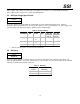
SSI ERP2U Power Supply Design Guide, V1.0 8.3.3.2 Asset Tag {Not used, code is zero length byte} FRU File ID {Not required} PAD Bytes {Added as necessary to allow for 8-byte offset to next area} MultiRecord Area As defined by the IPMI FRU document. The following record types shall be used on this power supply: • • • Power Supply Information (Record Type 0x00) DC Output (Record Type 0x01) No other record types are required for the power supply.
SSI ERP2U Power Supply Design Guide, V1.0 8.4 STATUS LED Indicators Required There shall be a single bi-color LED OR two LEDs, one AMBER and one GREEN, on each hot swap power module to indicate power supply status. When AC is applied to the power supply and standby voltages are available the GREEN LED shall BLINK. The GREEN LED shall turn ON to indicate that all the power outputs are available.
SSI ERP2U Power Supply Design Guide, V1.0 9 MTBF STATUS Recommended The power module shall have a minimum MTBF at continuous operation of 1) 50,000 hours at 100% load and 45 °C, as calculated by Bellcore RPP, or 2) 100,000 hours demonstrated at 100% load and 50 °C.