
User's Manual


SSI
ERP2U Power Supply Design Guide, V1.0
- 13 -
6 DC Output Specification
These are the output requirements for the power supply assembly including cage and module.
6.1 Output Connectors
The power supply assembly shall have the following output connectors and wire harness configuration.
6.1.1 Required Baseboard power connector
Connector housing: 24-Pin Molex
39-01-2240 or equivalent
Contact: Molex
44476-1111 or equivalent
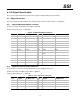
Table 6: P1 Baseboard Power Connector
Pin Signal 18 AWG Color Pin Signal 18 AWG Color
1 +3.3 VDC Orange 13 +3.3 VDC Orange
2 +3.3 VDC Orange 14 -12 VDC Blue
3 COM Black 15 COM Black
4 +5 VDC Red 16 PS_ON Green
5 COM Black 17 COM Black
6 +5 VDC Red 18 COM Black
7 COM Black 19 COM Black
8 PWR OK Gray 20 Reserved (-5 V in
ATX)
N.C.
9 5 VSB Purple 21 +5 VDC Red
10 +12 V2 Yellow/Blue Stripe 22 +5 VDC Red
11 +12 V2 Yellow/Blue Stripe 23 +5 VDC Red
12 +3.3 VDC Orange 24 COM Black
6.1.2 Optional Processor Power Connector
This connector is needed for systems with dual processors at higher power levels.
Connector housing: 8-Pin Molex 39-01-2080 or equivalent
Contact: Molex
44476-1111 or equivalent
Table 7: Processor Power Connector
Pin Signal 18 AWG color Pin Signal 18 AWG Color
1 COM Black 5 +12 V1 Yellow/Black Stripe
2 COM Black 6 +12 V1 Yellow/Black Stripe
3 COM Black 7 +12 V1 Yellow/Black Stripe
4 COM Black 8 +12 V1 Yellow/Black Stripe