
User's Manual

SSI
ERP2U Power Supply Design Guide, V1.0
- 7 -
4 Mechanical Overview
STATUS
Required (Optional)
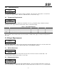
Note: Some features are noted as optional in the enclosure drawing figure below. These features may be use in
some chassis designs where only top access is allowed for the cage mounting.
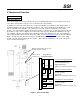
The ERP2U is a power sub-system made up of a cage and redundant, hot swappable power supply modules. A
mechanical drawing of the cage is shown below in Figure 1. This cage is intended to be mounted in the system
and not redundant or hot swappable. The exterior face of the cage accepts hot swappable power supply
modules. The cage distributes output power from the modules to a wire harness. Cooling fans may be located in
the modules or cage. If the cooling fans are located in the cage, they may optionally be redundant. If the cage
has redundant cooling the cage depth may be extended to allow for the additional series fan. A recommended
power supply module solution is the SSI TPS power supply. Refer to www.ssiforum.org for the latest TPS Design
Guide. The cage may have IEC inlet connector(s) and EMI filtering to distribute AC power to the power supply
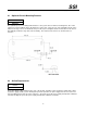
modules or the AC may plug directly into the modules. Three different configurations of the power sub-system
are also shown below in Figure 1.
Figure 1: Enclosure Drawing
Power Module
Configuration Options
Module
Module
AC
AC
Module
AC
Module
AC
Module
Module
AC
AC
SSI TPS Power Supply Configuration
No Fans in modules
AC inlets and EMI filter in cage
Optional Dual AC Inlets
Optional 3.3V, 5V DC/DC converters in cage
Vertical Power Supply Configuration
Fans in modules
AC inlets on modules
Dual AC Inlets
Optional 3.3V, 5V DC/DC converters in cage
Horizontal Power Supply Configuration
Fans in modules
AC inlets on modules
Dual AC Inlets
Optional 3.3V, 5V DC/DC converters in cage
Allow for 1.2mm
protrusion (x4)
Optional mounting features for top access
mounting of the power supply.