32882 USER'S MANUAL Of Intel H55 Express Chipset Based M/B for Intel LGA 1156 Processors NO. G03-HI06-F Rev: 1.0 Release date: February, 2010 Trademark: * Specifications and Information contained in this documentation are furnished for information use only, and are subject to change at any time without notice, and should not be construed as a commitment by manufacturer.
Environmental Protection Announcement Do not dispose this electronic device into the trash while discarding. To minimize pollution and ensure environment protection of mother earth, please recycle.
TABLE OF CONTENT ENVIROMENTAL SAFETY INSTRUCTION...............................................................iii USER’S NOTICE .......................................................................................................iv MANUAL REVISION INFORMATION........................................................................iv COOLING SOLUTIONS.............................................................................................
Environmental Safety Instruction Avoid the dusty, humidity and temperature extremes. Do not place the product in any area where it may become wet. 0 to 40 centigrade is the suitable temperature. (The figure comes from the request of the main chipset) Generally speaking, dramatic changes in temperature may lead to contact malfunction and crackles due to constant thermal expansion and contraction from the welding spots’ that connect components and PCB.
USER’S NOTICE COPYRIGHT OF THIS MANUAL BELONGS TO THE MANUFACTURER. NO PART OF THIS MANUAL, INCLUDING THE PRODUCTS AND SOFTWARES DESCRIBED IN IT MAY BE REPRODUCED, TRANSMITTED OR TRANSLATED INTO ANY LANGUAGE IN ANY FORM OR BY ANY MEANS WITHOUT WRITTEN PERMISSION OF THE MANUFACTURER. THIS MANUAL CONTAINS ALL INFORMATION REQUIRED FOR THE UTILIZATION OF THESE MOTHER-BOARDS TO MEET THE USER’S REQUIREMENTS. BUT IT WILL CHANGE, CORRECT AT ANY TIME WITHOUT NOTICE.
Chapter 1 Introduction of H55 Express Chipset Motherboards 1-1 Features of Motherboard The H55 Express chipset based motherboard series are based on Intel H55 Express chipset technology which supports the innovative Intel LGA 1156 socket Intel® Core™ i7 Quad Processor、Intel® Core™ i5 Quad Processor、Intel® Core™ i3 Dual Processor and Intel® Pentium Processor.
the demands of the next generation computing. But if you insist to gain more system performance with variety possibilities of the components you choose, please be careful and make sure to read the detailed descriptions of these value added product features, please get them in the coming section. 1-1.1 Special Features of motherboard CPU Smart Fan--- The Noise Management System It’s never been a good idea to gain the performance of your system by sacrificing its acoustics.
DIY Clear This CMOS Buttons (CMOS1) is to facilitate the clear COMS process for power user overclocking function. The user can easily clear or restore COMS settings by pressing down the button, without taking trouble to remove the case and locate the jumper for clear CMOS.
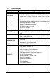
1-2 Specification Spec Design Chipset CPU Socket Memory Sockets Expansion Slots Description ATX form factor 4 layers PCB size: 30.5x24.5cm Intel H55 Express Chipset Intel LGA 1156 socket Intel® Core™ i7 Quad Processor、 Intel® Core™ i5 Quad Processor、Intel® Core™ i3 Dual Processor and Intel® Pentium Processor DDRIII module sockets x 4 Support 4pcs DDRIII 1066MHz/ DDRIII 1333 MHz memory modules expandable to 16GB. Support Dual- channel function PCI-Express2.
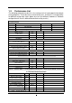
1-3 Performance List The following performance data list is the testing result of some popular benchmark testing programs. These data are just referred by users, and there is no responsibility for different testing data values gotten by users (the different Hardware & Software configuration will result in different benchmark testing results.
1-4 Layout Diagram VGA Connector PS/2 Mouse Connector ) ESATA RS-OUT Line-OUT Coaxial SPDIF_OUT HDMI Connector Line-IN RJ-45 LAN CS-OUT PS/2 Keyboard Connector SS-OUT ) DVI Connector USB Connectors USB Connectors ATX 12V Power Connector CPUFAN1 G.P.I LED PS/2 KB/MS ports HDMI Connector MIC-IN JP11 CPU Socket VGA Connector Over DVI Connector ESATA port over USB ports Coaxial SPDIF_OUT Connector RJ-45 Over USB Connector DDR3 Socket x 4 (DIMM1~DIMM4) E-SATA1 JP2 ATX Power Conn.
Jumpers Jumper JBAT JP11 JP2 JP6/JP7/JP8/JP9 JP10 Name Description 2-pin Block 3-pin Block 3-pin Block 3-pin Block 3-pin Block CMOS RAM Clear KB/MS Power On Enabled/Disabled USB Power On Enabled/Disabled PE1/MINIPCI-E select MINIPCI-E 3VSB/VCC3 select Sockets and Slots Socket/Slot CPU Socket DIMM1~DIMM4 PCI1,PC2 PE1 PE2,PE3 Name LGA 1156 CPU Socket DDRIII Module Sockets PCI Slots PCI-Express2.0 x 1 Slot PCI-Express 2.
Chapter 2 Hardware Installation WARNING! 2-1 Turn off your power when adding or removing expansion cards or other system components. Failure to do so may cause severe damage to both your motherboard and expansion cards. Hardware installation Steps Before using your computer, you had better complete the following steps: 1. Check motherboard jumper setting 2. Install CPU and Fan 3. Install System Memory (DIMM) 4. Install Expansion cards 5. Connect IDE Front Panel /Back Panel cable 6.
(2) KB/MS Power on Function Enabled/Disabled: JP11 JP11 JP11 2-3 Closed KB/MS Power ON Enabled 1-2 Closed KB/MS Power ON Disable (Default) Keyboard/Mouse Power On Setting (3) USB Power On function Enabled/Disabled: JP2 JP2 1-2 closed (Default) JP2 USB Power On Disable 2-3 closed USB Power On Enabled USB Power-On Setting (4) MINIPCI-E 3VSB/VCC3 Select: JP10 JP10 JP10 1-2 Close 3VSB 2-3 Close VCC3 :JP6/JP7/JP8/JP9 (5) PE1/MINIPCI-E Select: JP6/JP7/JP8/JP9 1-2 Close(all) Close(all): (all):
2-3 Installing CPU 2-3-1 Glossary Chipset (or core logic) - two or more integrated circuits which control the interfaces between the system processor, RAM, I/O devises, and adapter cards. Processor slot/socket - the slot or socket used to mount the system processor on the motherboard. Slot (PCI-E, PCI, RAM) - the slots used to mount adapter cards and system RAM.
has a corner pin for two of the four corners, the CPU will only fit in the orientation as shown. When you install the CPU into the LGA 1156 socket, there’s no force required CPU insertion; then press the level to locate position slightly without any extra force. Pin-1 Indicator Alignment key 2-3-3 1. LGA 1156 CPU Installation Guide 2. Press down the level and move it to the left side Please make sure that CPU socket is facing towards you and the level is on you left hand side.
the CPU socket). PinPin-1 Indicator Alignment Key Alignment Key 5. Make sire that golden finger in the right place as shown in the above illustration and match the two alignment keys on the CPU with two points of the socket. CPU can only be correctly installed with this direction. Incorrect installation might cause damage to CPU. 6.Put down the load plate in the direction shown above. 7. Press down the load level and move it rightwards make sure it is locked under the notch.
Motherboard 3. Press down two fasteners down in the 4. Turn over the motherboard carefully to oblique crossing direction as shown above. make sure the fastener insert in the right direction. Notice: Please apply thermal interface material to the CPU HIS surface. The heat sink and installation steps are for reference use only; Installation steps might differ depending on different heat sink models.
Install DDR SDRAM modules to your motherboard is not difficult, you can refer to figure below to see how to install DDRIII 1066/DDRIII 1333 SDRAM module. DIMM3 (BANK4+BANK5) DIMM4 (BANK6+BANK7) DIMM1 (BANK0+BANK1) DIMM2 (BANK2+BANK3) DIMM1 & DIMM3: Dual Channel 1 DIMM2 & DIMM4: Dual Channel 2 Graph 2-4 Installation Tips: : Open the two plastic clips of memory slots then push down the module vertically into the slot. See to it that the hole of the module fit into the notch of the slot.
4* 5* 6* 7* 8 9* 10 * 11 * 12 * 13 14 * 15 * 9 6 11 7 N/A 10 3 2 4 N/A 5 1 Communications Port (COM1) Sound Card (sometimes LPT2) Floppy Disk Controller Printer Port (LPT1) System CMOS/Real Time Clock ACPI Mode when enabled IRQ Holder for PCI Steering IRQ Holder for PCI Steering PS/2 Compatible Mouse Port Numeric Data Processor Primary IDE Channel Secondary IDE Channel * These IRQs are usually available for ISA or PCI devices.
2-5-4 Installing the CrossFire Bridge Card The following illustrations show you how to install the CrossFire Bridge Card. In order to activate the CrossFire technology, you have to install the optional Bridge for your CrossFire Tech. Supported VGA Cards before you activating the advance multi-GPUs functions. CrissFire Bridge Installation Reference 1. Install your CrossFire Tech Supported VGA Cards in the PCI-E x16 slots. 2. Prepare with the CF Bridges with your crossFire Tech Supported VGA Cards. 3.
2-6 Connectors, Headers 2-6-1 Connectors (1) Power Connector (24-pin block): ATXPWR ATX Power Supply connector: This is a new defined 24-pins connector that usually comes with ATX case. The ATX Power Supply allows using soft power on momentary switch that connect from the front panel switch to 2-pins Power On jumper pole on the motherboard.
(2) ATX 12V Power Connector (8-pin block) : ATX12V This is a new defined 8-pin connector that usually comes with ATX Power Supply. The ATX Power Supply which fully supports LGA 1156 processor must including this connector for support extra 12V voltage to maintain system power consumption. Without this connector might cause system unstable because the power supply can not provide sufficient current for system.
SS-OUT: (GRAY) Side-Surround audio output VGA Connector PS/2 Mouse Connector ) ) ESATA Coaxial SPDIF_OUT HDMI Connector Line-IN RS-OUT Line-OUT CS-OUT PS/2 Keyboard Connector SS-OUT DVI Connector USB Connectors USB Connectors MIC-IN (8) Serial-ATA2 Port connectors: SATA1~SATA6 These connectors support the provided Serial ATA and Serial ATA2 IDE hard disk cable to connect the motherboard and serial ATA2 hard disk drives.
2-6-2 Headers AU D I O KEY LINE2-JD Audio-JD MIC2-JD Audio-GND (1) Line-Out/MIC Header for Front Panel (9-pin): FP_AUDIO These headers connect to Front Panel Line-out, MIC connector with cable. 2 10 P in 1 Sense-FB Lineout2-L Lineout2 -R MIC2-L MIC2 -R 9 Line-O ut, MIC Headers VCC - DATA +DATA GND OC VCC -DATA +DATA GND (2) USB Port Headers (9-pin): USB2/USB3/USB4 These headers are used for connecting the additional USB port plugs.
GND PWRBTN PWRBTN PWR LED VCC5 JW FP PWRLED PWRLED Pin 1 SPEAK VCC5 HDDLE GND RSTSW NC HDLED RESET GND VCC5 Pin 1 SPKR NC Pin 1 System Case Connections (8) FAN Headers: SYSFAN1 (3-pin), SYSFAN2 (3-pin), CPUFAN (4-pin) These connectors support cooling fans of 350mA (4.2 Watts) or less, depending on the fan manufacturer, the wire and plug may be different. The red wire should be positive, while the black should be ground.
+5VX GND IR1 2 6 GN D IRTX 5 IRRX Pin 1 IR infrared module Headers (11) Serial COM Port header: COM1 COM1 is a 9-pin RS232 connector. Pin1 Serial COM Port 9-pin Block (12) SPDIF Out header: HDMI_SPDIF The SPDIF output is capable of providing digital audio to external speakers or compressed AC3 data to an external Dolby digital decoder. Use this feature only when your stereo system has digital input function.
2-7 Starting Up Your Computer 1. After all connection is made, close your computer case cover. 2. Be sure all the switch are off, and check that the power supply input voltage is set to proper position, usually in-put voltage is 220V∼240V or 110V∼120V depending on your country’s voltage used. 3. Connect the power supply cord into the power supply located on the back of your system case according to your system user’s manual. 4. Turn on your peripheral as following order: a. Your monitor. b.
Chapter 3 Introducing BIOS The BIOS is a program located on a Flash Memory on the motherboard. This program is a bridge between motherboard and operating system. When you start the computer, the BIOS program will gain control. The BIOS first operates an auto-diagnostic test called POST (power on self test) for all the necessary hardware, it detects the entire hardware device and configures the parameters of the hardware synchronization.
3-3 The Main Menu Once you enter AMI BIOS Setup Utility, the Main Menu (Figure 3-1) will appear on the screen. The Main Menu allows you to select from 12 setup functions and 2 exit choices. Use arrow keys to select among the items and press to accept or enter the sub-menu. Figure 3-1 Standard BIOS Features Use this Menu for basic system configurations. Advanced BIOS Features Use this menu to set the Advanced Features available on your system.
Change Supervisor Password This entry is for setting Supervisor password. Change User Password This entry for setting User password Save Changes and Exit Save CMOS value changes to CMOS and exit setup. Discard Changes and Exit Abandon all CMOS value changes and exit setup. 3-4 Standard BIOS Features The items in Standard CMOS Setup Menu are divided into several categories. Each category includes no, one or more than one setup items.
Bit Data Transfer The optional settings are: Disabled and Enabled. System Memory This item will show information about the memory modules(s) installed. 3-5 Advanced BIOS Features Boot Sector Virus Protection The selection Allow you to choose the VIRUS Warning feature for IDE Hard Disk boot sector protection. If this function is enabled and someone attempt to write data into this area, BIOS will show a warning message on screen and alarm beep.
3-5-1 CPU Features C1E Function This should be enabled in order to enable or disable the “Enhanced Halt State”. The optional settings are: Enabled; Disabled. Hardware Prefetcher For UP platform, leave it as Enabled. For DP/MP servers, it may use to tune performance to the specific application. The optional settings are: Enabled; Disabled. Adjacent Cache Line Prefetch For UP platform, leave it as Enabled. For DP/MP servers, it may use to tune performance to the specific application.
Intel(R) SpeedStep (tm)tech The optional settings are: Enabled; Disabled. Disable: Disable GV3. Enabe: Enable GV3. InteL(R) TurboMode tech Turbo mode allows processor cores to run faster than marked frequency in specific condition. Intel(R) C-STATE tech CState: CPU idle is set to C2/C3/C4. 3-6 Advanced Chipset Features The Advanced Chipset Features Setup option is used to change the values of the chipset registers. These registers control most of the system options in the computer.
3-7 Integrated Peripherals Configure SATA as Press Enter to select the SATA type. The optional settings are: IDE; AHCI and Disabled. SATA#1 IDE Configuration The optional settings are: Compatible and Enhanced. SATA#2 IDE Configuration The optional settings are: Disabled and Enhanced. Onboard PCIE Lan Controller Use this item to enable or disable onboard PCIE Lan controller. Onboard PCIE Lan BootROM The optional settings are: Disabled; Enabled. USB Functions The optional settings are: Disabled; Enabled.
3-8 Power Management Setup The Power Management Setup allows you to configure your system to most effectively save energy saving while operating in a manner consistent with your own style of computer use. ACPI Version Features The optional settings are: ACPI v1.0; ACPI v2.0; ACPI v3.0. ACPI APIC Support Include ACPI APIC table pointer to RSDT pointer list. AMI OEMB Table Include OEMB table Pointer to R(X) SDT pointer lists. Headless Mode Enable/Disable headless operation through ACPI.
Disabled. High Performance Event Timer The optional settings are: Enabled; Disabled. Resume On RTC Alarm Use this item to disable or enable RTC to generate a wake event. 3-9 Miscellaneous Control Palette Snooping The optional settings are: Enabled; Disabled. Enable: inform the PCI device that an ISA graphics devices is installed in the system so the card will function correctly. 3-10 PC Health Status This section shows the Status of you CPU, Fan, and Warning for overall system status.
3-10-1 Smart FAN Configuration FAN1/FAN2 Mode Setting Press enter to select FAN1/FAN2 Mode setting, the optional settings are: Auto Fan by RPM; Auto Fan by DutyCycle; Manual Mode by RPM; Manual Mode by DutyCycle. 3-11 User Overclock Settings Linear PCIEX Clock Use this item to set Linear PCIEX clock in the range of 100 to 200. CPU Diff AMP The optional settings are: 700mV; 800mV; 900mV; 1000mV. PCIEX Diff AMP The optional settings are: 700mV; 800mV; 900mV; 1000mV.
CPU Clock Skew The optional settings are: Default; 100ps~1500ps. DRAM Clock at Next Boot The optional setting are: Auto; 800MHz (DDR3 800); 1066 MHz (DDR3 1066); 1333MHz (DDR3 1333). Host/PCI Clock at Next Boot Use the item to set CPU Frequency. Range between 133~500. CPU Vcore 7-Shift Use this item to set value in CPU Vcore 7-Shift function. optional settings are: +50mV to 350mV. CPU PLL Select Use this tem to set CPU PLL from 1.816V (Default) to 2.043V.
3-12 Password Settings You can set either supervisor or user password, or both of them. The differences are: Change Supervisor password: Can enter and change the options of the setup menus. Change User password: Can only enter but do not have the right to change the options of the setup menus. When you select this function, the following message will appear at the center of the screen to assist you in creating a password.
Pressing loads the default values that are factory settings for stable performance system operations. 3-14 Save Changes and Exit / Discard Changes and Exit Save Changes and Exit When you press on this item, you get a confirmation dialog box with a message similar to: Pressing save the values you made previously and exit BIOS setup.
Chapter 4 Driver & Free Program Installation Check your package and there is A MAGIC INSTALL CD included. This CD consists of all DRIVERS you need and some free application programs and utility programs. In addition, this CD also include an auto detect software which can tell you which hardware is installed, and which DRIVERS needed so that your system can function properly. We call this auto detect software MAGIC INSTALL.
11. EXIT to exit from MAGIC INSTALL menu 4-1 INF Install Intel H55 Chipset System Driver 1.Click INF item when Magic Install menu 2 . Click Next when Intel Chipset Device appears. Software appears. 3. Click Yes on the License Agreement. 4. After reading the Readme File Information click Next. 5. Click Next. 6.Click Finish to finish installation.
4-2 SOUND Install ALC HD Audio Codec Driver 1. Click Sound on the Magic Install menu. 2.lick Next When Realtek High Definition Audio driver windows appear 3. Click Finish and restart your computer 5. The mixer. 4. Manual Sound Effect Setting 6. Audio input and output settings.
7. Microphone effect. 8. 3D sound effect.. NOTE: Please upgrade your Windows XP to Service Pack to Service Pack 4 or later before you the HD Audio CODEC driver. 4-3 RealTek Install Realtek Gigabit Ethernet NIC Driver 1. Click LAN when Magic Install Menu appears 3. Click install to begin the installation. 2. Click Next, install REALTEK LAN and Fast Ethernet NIC Driver 4. After driver installation completed, Click Finish.
4-4 Norton Install Norton Internet Security 2010 1. Click Norton when Magic Install menu 2. Click AGREE & INSTALL after reading appears. 4-5 PC-health Unser License Agreement. Install MyGuard Hardware Monitor Utility 1. Click PC-Health when MAGIC INSTALL MENU appears 2. Click Next when Install shield wizard Window appears. 3. Click Install to begin the installation. 4. Click Finish to complete the installation.
4-6 VGA Install Intel HD VGA Driver 1. Click VGA when MAGIC INSTALL MENU 2. Click Next to continue. appears. 3. Accept the license agreement and Click 4. Click next. yes. 5. Click next to continue. 6. Click finish.
4-7 DOTNET Install DOTNET 1. Click DOTNET when MAGIC INSTALL MENU appears. 2. choose “ I have read and accept the terms of the license agreement. 3. download and install progress. 4. setup complete and Click Exit. 4-8 IMSS Install IMSS 1. Click IMSS when MAGIC INSTALL MENU 2. Click Next. appears.
3. Click Yes. 4. Click Next. 5. Click Next to continue. 6. Click finish to complete the setup process. 4-9 AHCI/RAID Install Intel AHCI /RAID Driver If you want to use Intel SATA AHCI mode for your system, please according to following steps to install driver: 1. Copy CD: \intel5x\pch_ahci_raid\f6flpy32 all files to empty boot disk root directory. (For windows XP / vistaX32) Copy CD: \intel5x\pch_ahci_raid\f6flpy64 all files to empty boot disk root directory. (For windows xp64 / vistaX64) 2.
driver First. 4. If you are Windows 7 /Vista OS, please load SATA ACHI driver from this location. NOTICE! The above driver screen and operation steps are for reference only because we might update the drivers or make modifications due to technological need and user’s benefits. We reserve these changes or upgrade without advanced notification. Please visit our website for possible driver upgrade. 4-10 How to Update BIOS STEP 1. Prepare a bootable disk.
software. If user does not want to keep the software, just reboot the computer to restore back to the previous state, and Pro Magic will remove it completely from you computer. Password Security – Pro Magic provides double password protection, including user password for entering each OS and manager password for managing ‘Pro Magic’, which can effectively prevent others from using your computer without permission or data from being stolen.
4-12 G.P.I. Function LED Display PWS_LED1 PWS_LED2 PWS_LED3 PWS_LED4 All LED off or glitter. It means the motherboard in the G.P.I mode. CPU works with the low power consumption. PWS_LED1 PWS_LED2 PWS_LED3 PWS_LED4 Three LED off or glitter. It means the motherboard is working on partial power saving mode. (The LED off indicate the relative power phase working with idle mode). PWS_LED1 PWS_LED2 PWS_LED3 PWS_LED4 Three LED on. It means the motherboard is working on partial power saving mode.