
Guidelines
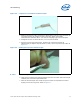
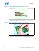
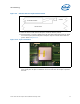
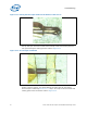
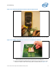
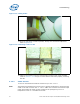
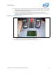
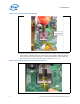
Table Of Contents
- 1 Introduction
- 2 Packaging Technology
- 3 Thermal Specifications
- 4 Thermal Simulation
- 5 Thermal Metrology
- 6 Reference Thermal Solution
- A Thermal Solution Component Suppliers
- B Mechanical Drawings
Intel® 3210 and 3200 Chipset Thermal/Mechanical Design Guide 23
Thermal Metrology
3. Measure the thermocouple resistance by holding both contacts on the connector on
one probe and the tip of thermocouple to the other probe of the DMM
(measurement should be about ~3.0 ohms for 36-gauge type T thermocouple).
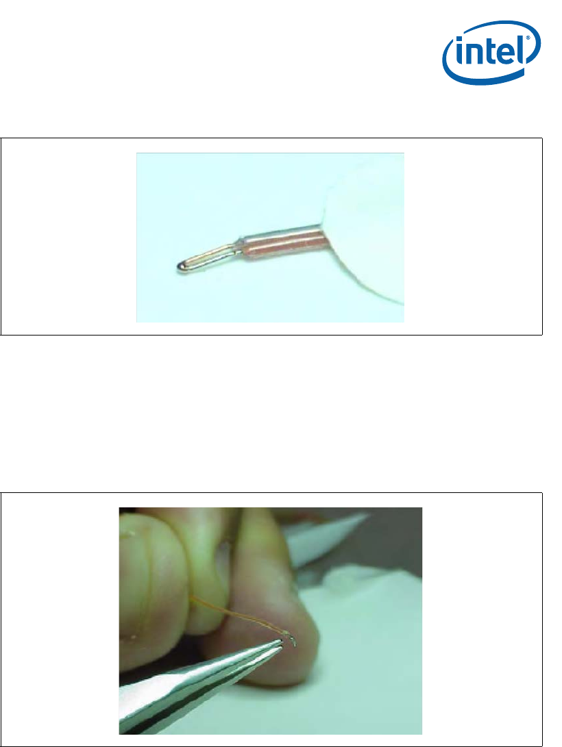
4. Straighten the wire for about 38 mm [1.5 inch] from the bead.
5. Using the microscope and tweezers, bend the tip of the thermocouple at
approximately 10 degree angle by about 0.8 mm [.030 inch] from the tip. Refer to
Figure 5-6.
5.1.4.2 Thermocouple attach to the IHS
6. Clean groove and IHS with Isopropyl Alcohol (IPA) and a lint free cloth removing all
residues prior to thermocouple attachment.
7. Place the Thermocouple wire inside the groove and let the exposed wire extend
slightly over the end of groove. Refer to Figure 5-7.
Figure 5-5. Inspection of Insulation on Thermocouple
Figure 5-6. Bending the Tip of the Thermocouple