
Guidelines
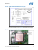
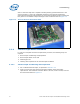
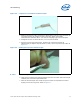
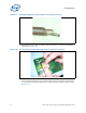
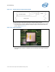
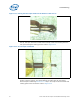
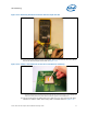
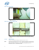
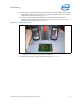
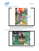
Table Of Contents
- 1 Introduction
- 2 Packaging Technology
- 3 Thermal Specifications
- 4 Thermal Simulation
- 5 Thermal Metrology
- 6 Reference Thermal Solution
- A Thermal Solution Component Suppliers
- B Mechanical Drawings
Intel® 3210 and 3200 Chipset Thermal/Mechanical Design Guide 25
Thermal Metrology
10.Place the device under the microscope to continue with the process.
11.Using tweezers or a finger, slightly press the wire down inside the groove for about
5 mm from tip and place small piece of Kapton* tape to hold the wire inside the
groove. Refer to Figure 5-10.
12.Thermocouple bead is placed into the bottom of the groove (Refer to Figure 5-11)
and a small piece of tape is installed to secure it under the microscope to perform
this task.
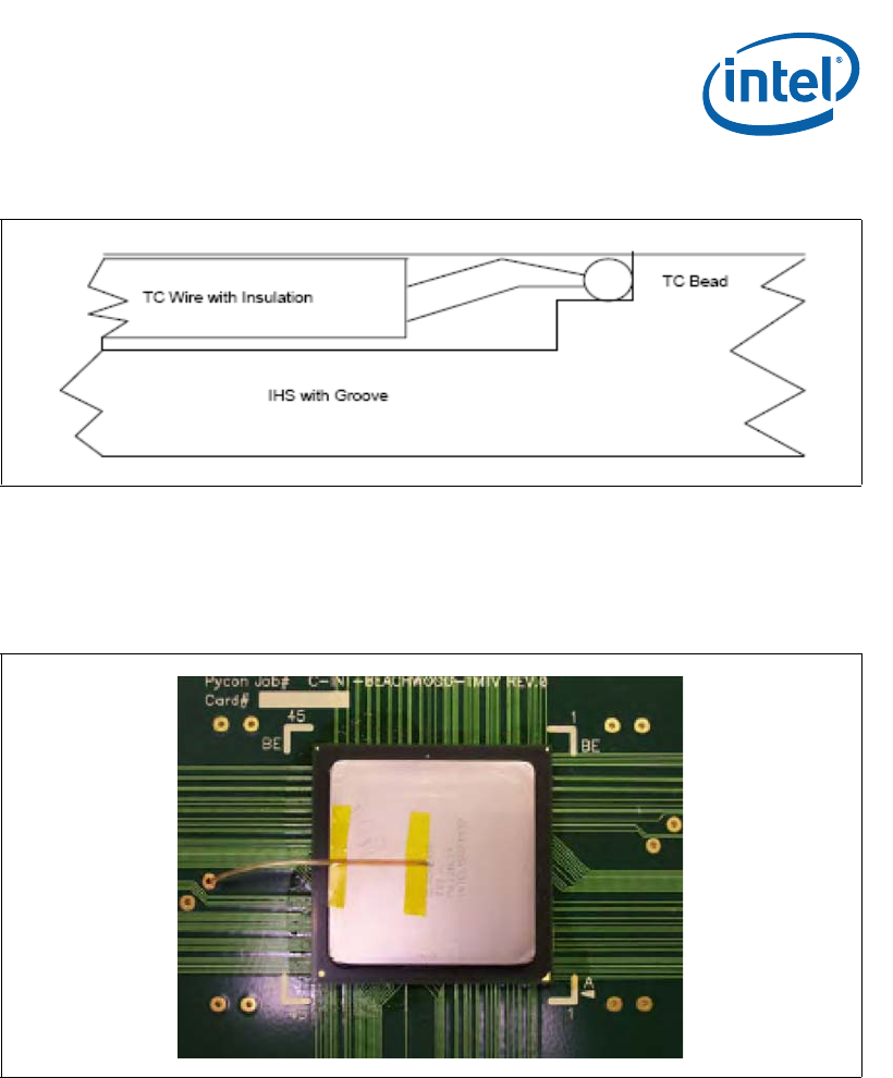
Figure 5-9. Detailed Thermocouple Bead Placement
Figure 5-10. Tapes Installation