
Intel Core2 Duo Desktop Processor, Intel Pentium Processor, and Intel Pentium 4 Processor 6x1 Sequence

Legacy Fan Speed Control
108 Thermal and Mechanical Design Guidelines
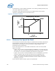
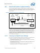
for TDP power at a given ambient temperature. The resulting variable speed fan (VSF)
curve is the upper limit on fan speed.
The benefit of this upper limit will become more apparent when the fan speed
controller is responding to the on-die thermal sensor.
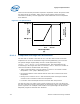
Figure 61. Thermistor Set Points
Fan Speed
(RPM)
Fan Inlet
Temperature (°C)
Full
Speed
30
38
Min.
Operating
Variable Speed Fan (VSF) Curve
Fan Speed
(RPM)
Fan Inlet
Temperature (°C)
Full
Speed
30
38
Min.
Operating
Variable Speed Fan (VSF) Curve
E.1.2 Minimum Fan Speed Set Point
The final aspect of thermal solution design is to determine the minimum speed the fan
will be allowed to operate. This value can be driven by the cooling requirements for
another portion of the design, such as the processor voltage regulator, or by
functional limits of the fan design.
Per the Fan Specification for 4 wire PWM Controlled Fans; there are three possible
options to consider
• Type A: The fan will run at minimum RPM for all PWM duty cycle values less than
minimum duty cycle. This would be programmed into the fan controller located on
the fan hub. It can not be overridden by the external fan speed control.
• Type B: The fan will run at minimum RPM for all non-zero PWM duty cycle values
less than minimum duty cycle and turn off the fan at 0% PWM duty cycle.
• Type C: The fan will stop running when the current provided to the motor
windings is insufficient to support commutation. The fan would turn off at 0%
PWM duty cycle input.
For the reference thermal solution Type A was implemented.