
Intel Core2 Duo Desktop Processor, Intel Pentium Processor, and Intel Pentium 4 Processor 6x1 Sequence

Legacy Fan Speed Control
Thermal and Mechanical Design Guidelines 109
E.2 Board and System Implementation
Once the thermal solution is defined, the system designer and board designer can
define the fan speed control implementation. The first step is to select the appropriate
fan speed controller (FSC).
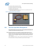
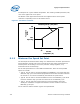
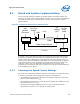
Figure 62 shows the major connections for a typical
implementation.
Figure 62. Example Fan Speed Control Implementation
HS Fan
Processor
ICH8 / ME
PWM
Tachometer
Digital Thermal Sensor
+12V
GND
Sys
Ambient
(SST)
Sys Fan
4wire
PWM
T
CONTROL
BIOS
Inlet
Ambient
(Thermistor
)
4-Pin Fan
Header
A number of major manufacturers have FSC components that include the necessary
functionality to measure the temperature of the digital thermal sensor via the PECI
interface and output a PWM signal. These components can be a discrete device or a
super IO (SIO) with the functionality embedded. Intel has engaged with a number of
major manufacturers of FSC components to provide devices that have a PECI host
controller. Contact your Intel Field Sales representative for the current list of
manufacturers and visit their web sites or contact your local sales representatives for
a part suitable for your design.
E.2.1 Choosing Fan Speed Control Settings
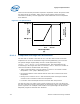
Fan speed control algorithms allow the system thermal engineer a number of options
to consider. The typical control settings that need to be considered are:
• The temperature when the fan will begin to accelerate in response to the on-die
thermal sensor temperature (T
LOW
)
• The temperature where the fan is operating at full speed (100% PWM duty cycle).
By specification this is T
CONTROL
.
• The minimum fan speed (PWM duty cycle). For any on-die thermal sensor
temperature less than T
LOW
, the fan will run at this speed