
Intel Core2 Duo Desktop Processor, Intel Pentium Processor, and Intel Pentium 4 Processor 6x1 Sequence

Intel® Enabled Balanced Technology Extended (BTX) Reference solution
Thermal and Mechanical Design Guidelines 51
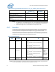
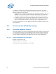
Table 7. Processor Preload Limits
Parameter Minimum Required Maximum
Allowed
Notes
Processor Preload 98 N [22 lbf] 222 N [50 lbf] 1
NOTE:
1. These values represent upper and lower bounds for the processor preload. The nominal
preload design point for the Thermal Module is based on a combination of requirements
of the TIM, ease of assembly and the Thermal Module effective stiffness.
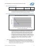
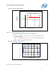
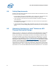
Figure 15. Minimum Required Processor Preload to Thermal Module Assembly Stiffness
NOTE:
1. The shaded region shown is the acceptable domain for Thermal Module assembly
effective stiffness and processor preload combinations. The Thermal Module design
should have a design preload and stiffness that lies within this region. The design
tolerance for the preload and TMA stiffness should also reside within this boundary.
Note that the lower and upper horizontal boundaries represent the preload limits
provided in
Table 7. The equation for the left hand boundary is described in note 2.
2. The equation for this section of the preload-Thermal Module stiffness boundary is given
by the following relationship: Min Preload = 1.38E-3*k^2 – 1.18486k + 320.24753 for
k < 300 N/mm where k is the Thermal Module assembly effective stiffness. Note that
this equation is only valid in the stiffness domain of 93N/mm < k < 282N/mm. This
equation would not apply, for example, for TMA stiffness less than 93N/mm.
3. The target stiffness for the 65 W Type II TMA reference design is 484 N/mm
(2764 lb / in).
Note: These preload and stiffness recommendations are specific to the TMA mounting
scheme that meets the BTX Interface Specification and Support Retention Mechanism
(SRM) Design Guide. For TMA mounting schemes that use only the motherboard
mounting hole position for TMA attach, the required preload is approximately 10–15N
greater than the values stipulated in
Figure 15; however, Intel has not conducted any
validation testing with this TMA mounting scheme.