Getting Started RAID Array 410 for Windows NT – Intel Installation Guide Order Number: EK–SMRAC-IG.
Third Edition, June 1996 The disclosure of this information does not grant to the user a license under any patents, pending patents, trademarks, or copyrights or other rights of Digital Equipment Corporation, or of any third party. This software is proprietary to and embodies the confidential technology of Digital Equipment Corporation.
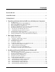
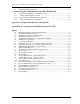
Contents Revision Record ...................................................................................................... v About This Guide.................................................................................................. vii Getting Started ...................................................................................................... ix 1 Unpacking and Setting Up Your RAID Array 410 Subsystem Components 1.1 1.2 1.3 1.4 1.5 1.6 1.6.1 1.6.2 1.7 1.8 1.9 Site Preparation .......
Getting Started - RAID Array 410 for Windows NT – Intel 3.7 Saving the RAID Configuration ............................................................................... 3–12 4 Completing your Configuration Setup under Windows NT 4.1 4.1.1 4.1.2 4.1.3 Completing Configurations under Windows NT ......................................................... 4–1 Verifying that hszdisk.sys Loaded...........................................................................
Revision Record This Revision Record provides a concise publication history of this manual. It lists the manual revision levels, release dates, and reasons for the revisions. It also describes how the changes to affected pages are marked in the manual. The following revision history lists all revisions of this publication and their effective dates. The publication part number is included in the Revision Level column, with the last entry denoting the latest revision.
About This Guide This section identifies the audience of this guide and describes the contents (chapter by chapter) and structure. In addition, this section includes a list of associated documents and the conventions used in this guide. This guide provides the following: • Description of how to unpack and assemble the RAID Array 410 Subsystem • How to install the Host Adapter board into your Intel-based system. • Installing and using the RAID Array 410 Manager for Windows NT.
Getting Started - RAID Array 410 for Windows NT – Intel Appendix A: Configuration Record This appendix contains blank forms that may be used to provide a record of your system configuration. Appendix B: Accessing the Command Line Interpreter (CLI) This appendix contains procedures to access the RAID Array controller (SWXRC-04) Command Line Interpreter (CLI).
Getting Started This section provides an overview for preparing and installing the RAID Array 410 for Windows NT in your Intelbased system. Detailed information is contained in Chapters 1 through 5. Thank you for purchasing a StorageWorks RAID Array 410 Subsystem.
Getting Started - RAID Array 410 for Windows NT – Intel Installation “Checklist” This section expands upon the preceding steps to provide a “checklist” or “roadmap” to assist you during the installation process. Detailed procedures are provided in subsequent chapters in this guide. Depending upon your specific configuration requirements, however, you may not need to perform all the tasks identified: 1. Perform the pre-installation steps listed below (see this Getting Started chapter). 2.
Getting Started Verify User-Supplied Hardware and Software (System Requirements) The StorageWorks RAID Array 410 Subsystem requires the following user-supplied hardware and software: • Intel-based PCI or EISA system with an available PCI or EISA slot (depending upon the host adapter used) • The associated system hardware manual(s) • Appropriate tools to service your computer • The Windows NT operating system – Version 3.
1 Unpacking and Setting Up Your RAID Array 410 Subsystem Components This chapter describes the site preparation and unpacking procedures for the RAID Array 410 Subsystem. It also describes the procedure to recharge the controller write-back cache batteries. 1.1 Site Preparation Before installing the enclosure, make sure that adequate space is available in front of the enclosure for opening the front door (19 inches clearance) and around the enclosure for adequate airflow.
Getting Started - RAID Array 410 for Windows NT – Intel 1.2 Unpacking the RAID Array 410 (SWXRA-Yx) The RAID Array 410 is packed in a corrugated carton attached to a wooden shipping pallet, as shown in Figure 1–2A. Unpack the unit as follows: NOTE Before unpacking the equipment, inspect the shipping carton for signs of external damage. Report any damage to the local carrier and to your sales representative. 1. Remove the shipping straps (Figure 1–2A). 2. Remove the top cover (Figure 1–2B). 3.
Chapter 1. Unpacking and Setting Up Your RAID Array 410 Subsystem Components Figure 1–2 Unpacking the RAID Array 410 Figure 1–3 Installation of Ramp on Shipping Pallet EK–SMRAC–IG.
Getting Started - RAID Array 410 for Windows NT – Intel 3. Grasping the sheet metal base assembly, carefully lift the rear of the RAID Array 410 enclosure over the “hump” in the center of the pallet and then roll the RAID Array 410 enclosure off the pallet and down the ramp to the floor. If any further lifting of the RAID Array 410 is required, grasp the sheet metal base assembly on the side and lift it carefully. 4. Retain the shipping container and all packing materials. 1.
Chapter 1. Unpacking and Setting Up Your RAID Array 410 Subsystem Components Follow these electrostatic discharge (ESD) precautions when handling the PC (program) card. • Keep the PC (program) card in its original carrying case unless installing it. • Do not twist or bend the card. • Do not touch the contacts. • Keep out of direct sunlight. • DO NOT immerse the card in water or chemicals. • Always push the eject button to remove the card (see Figure 1–4).
Getting Started - RAID Array 410 for Windows NT – Intel 3. Replace the ESD shield over the PC (program) card. To do so, first ensure the ESD shield fastener shafts are extended outward, away from the contact surface of the ESD shield. Place the ESD shield over the PC card and eject button and insert the ESD shield fastener clasps in their mounting holes on the controller chassis. Then, gently push the fastener shafts inward, approximately one-eighth inch, to engage the fastener clasps.
Chapter 1. Unpacking and Setting Up Your RAID Array 410 Subsystem Components To install an SBB, hold it in both hands, insert it into the guide slots, and firmly push it into the shelf until the mounting tabs snap in place. Installing the SBBs in this sequence distributes the SBBs among the SCSI ports of the RAID Array 410. Figure 1–5 shows a layout of the SCSI bus ports and corresponding SCSI ID assignments in the enclosure.
Getting Started - RAID Array 410 for Windows NT – Intel 3. Apply power to the controller, by using the power switch on the AC Power Entry Controller. You should hear a momentary audible tone (beep), and see the indicator LEDs illuminate. In addition, the controller reset button (see Figure 1–4) contains a green LED, which should flash at approximately 1 Hz.
Chapter 1. Unpacking and Setting Up Your RAID Array 410 Subsystem Components Figure 1–6 SWXSC-AA Components (Cabinet removed for clarity) EK–SMRAC–IG.
2 Host Adapter Installation – Intel-based System In preparing your array for first time use, you need to connect your Intel-based system to the RAID subsystem through the host adapter board. This chapter, along with your system and the associated StorageWorks RAID Array 410 Subsystem manuals, provides instructions for preparing and installing the host adapter and the subsystem enclosure, and installing the appropriate drivers on the computer system..
Getting Started - RAID Array 410 for Windows NT – Intel You need the following before you begin: • The appropriate host adapter (SWIA3-BB or SWXA3-BC). Use precautions to protect the board from static discharge.
Chapter 2. Host Adapter Installation – Intel-Based System Connect the SCSI cable to the host adapter as shown in Figure 3–1. 3. The adapter is now physically installed. Later in the installation process, you will power on your system and load the appropriate software for the required host adapter drivers. Figure 2–1 Connecting SCSI Cable 2.2 Installing the Subsystem 1. Unlock the RAID Array Enclosure, if necessary, using the keys provided, and open the enclosure front door. 2.
Getting Started - RAID Array 410 for Windows NT – Intel Secure the SCSI cable to the trilink on the controller by tightening the two screws on the cable connector. Figure 2–2 SCSI Cable Connection to Controller (Single Controller) Figure 2–3 SCSI Cable Connection to Controller (Dual Controller) 2–4 EK–SMRAC–IG.
Chapter 2. Host Adapter Installation – Intel-Based System 4. Connect the power cable to the storage enclosure if it has not yet been installed. Do so by connecting the female end of the power cable to the RAID Controller power controller located at the lower right front corner of the array. Plug the power cable into a 110/220 VAC line voltage source (the power supply automatically senses the voltage level and will work with either voltage). 5.
Getting Started - RAID Array 410 for Windows NT – Intel After Windows NT is installed, replace the device driver and install the device driver with the one on the enclosed Windows NT disk. 2.4.2 Windows NT Previously Installed If Windows NT was already present on the system when the adapter was installed, you need to load the appropriate Adaptec adapter driver at this time. The Adaptec driver is contained on the Adaptec Windows NT diskette. To install the drivers, follows these steps: 1.
Chapter 2. Host Adapter Installation – Intel-Based System where: “drive_letter” and “NT_root_directory” correspond to the root path of your Windows NT system files on your system (e.g., hszinstl c:\winnt35). 6. The installation process copies the driver into the correct subdirectory and creates the necessary Registry entries. 2.
3 Installing and Using the RAID Manager for Windows NT This chapter contains instructions for installing the RAID Manager software, configuring the system, and creating an initial configuration. This chapter also contains sheets for recording your configuration. NOTE The procedures in this chapter assume that the write-back cache module batteries have been fully recharged, as described in Chapter 1 of this guide. If you have not yet recharged your writeback cache batteries, you should do so at this time.
Getting Started - RAID Array 410 for Windows NT – Intel 3.3 • Identify the controller as Model SWXRC-04. • Set up your initial RAID configuration using the RAID Manager. Installing the RAID Manager Software Locate the diskette, RAID 300, 400 Series for Windows NT RAID Manager, and insert it in your disk drive. Access Program Manager in Windows NT. From the Program Manager, click on File and select Run from the pull-down menu.
Chapter 3. Installing and Using the RAID Array 410 Manager for Windows NT Figure 3− − 2 The System ID Window 4. At the RAID Manager main window, again click on Settings. This time, from the list of choices in the Settings pull-down menu, select Controller Communications. The Controller Communications window opens. At the Controller Communications window, make the following selections: • Choose the COM port (COM1, COM2, COM3, etc.) used to connect to the SWXRC-04 maintenance port.
Getting Started - RAID Array 410 for Windows NT – Intel Select the choice, “D” for Host Functionality; this sets the controller to operate in Windows NT mode. This choice is required for the controller to operate correctly with Windows NT. Refer to the release notes for this product for more information. • Go to the bottom of the window and enter a value of 5 for the Cache Flush Timer/Timers.
Chapter 3. Installing and Using the RAID Array 410 Manager for Windows NT To help you get started, and to familiarize you with the manager, we have provided simplified practice examples for setting up an initial configuration. (Your display screens may look slightly different from those shown here, depending upon the version of your RAID Manager software.
Getting Started - RAID Array 410 for Windows NT – Intel 3. Return to the main window and again click on the Settings pull-down menu. This time, from the choices offered, choose Select Physical View and be sure to include SWXRC04 in the choice, so that the correct enclosure type will be displayed in the physical view. 4. Click on the Show Detail button to cause the physical view to be displayed. For our example, the following image is displayed (see Figure 3–4).
Chapter 3. Installing and Using the RAID Array 410 Manager for Windows NT Figure 3–5 Updated Physical View 3.6.2 Practice Example: Creating a Single Disk Click on the Configure button near the top of the main window. Doing so displays three configuration buttons in the right side of the window: Create, Modify, and CLI. To create a single disk, perform the following steps: 1. Click on the Create button. The Create button opens and displays the Create window (see Figure 3–5).
Getting Started - RAID Array 410 for Windows NT – Intel 2. For this example, select Single Disk - JBOD and choose a target ID (by default you can create up to eight logical units under a single ID). Click on OK. The RAID Manager responds by displaying a message window advising you to click on the disk we wish to use (in our physical view) for the single disk. In our example, we select (click on) the disk in the lower, left corner of the physical view. 3.
Chapter 3. Installing and Using the RAID Array 410 Manager for Windows NT The RAID Manager responds by displaying a message window advising you to click on at least two disks (in our physical view) to use for the Stripeset. 3. Select the disks to use for the Stripeset. In our example, we select (click on) the two bottom disks disk in the lower, right corner of the physical view. When finished, click on Create in the message window. The RAID Manager responds by updating the physical view (see Figure 3–8).
Getting Started - RAID Array 410 for Windows NT – Intel 2. For this example, select RAID 1 - Mirrorset, then, in the Set Name box, supply (enter) a name for the Mirrorset. For our example, the name is “Mirr1”. Click on OK when finished. The RAID Manager responds by displaying a message window advising you to click on at least two disks (in our physical view) to use for the Mirrorset. 3. Select the disks to use for the Mirrorset.
Chapter 3. Installing and Using the RAID Array 410 Manager for Windows NT 2. Choose (click on) Spare from the choices listed, then click on OK. When the physical view window opens, click on the disk to be identified as a spare, then Create. 3.6.6 Practice Example: Deleting Storagesets To delete storageset elements, perform the following steps: 1. Select the Configuration pull down menu.
Getting Started - RAID Array 410 for Windows NT – Intel NOTE After saving (or recording) your configuration, you must reboot your system, then use Windows NT Disk Administrator to complete the configuration under Windows NT. Doing so ensures that Windows NT recognizes the partition/format configuration information. You must also use Windows NT Disk Administrator to complete the configuration under Windows NT when changes are made to the configuration.
Chapter 3. Installing and Using the RAID Array 410 Manager for Windows NT Record the information in the following table: Date__________________ Name of RAIDset EK–SMRAC–IG.
4 Completing your Configuration Setup under Windows NT This chapter contains instructions for how to complete your configuration set up through Disk Administrator under Windows NT. 4.1 Completing Configurations under Windows NT In order for Windows NT to recognize new RAID Array 410 devices or changes to existing configurations, you must reboot your system to restart Windows NT. 4.1.1 Verifying that hszdisk.
Chapter 4. Completing Your Configuration Setup Under Windows NT If an entry for hszdisk appears with a 1 in the Event column, similar to the screen shown Figure 4−2, the hszdisk did not load successfully due to its not finding any logical drives. If the hszdisk did not load successfully, go to Chapter 3 of this guide, and reconfigure the array. If after reconfiguring the array, hszdisk still fails to load, contact your Sales Representative. Figure 4− − 2 How The hszdisk Entry Appears When It Fails To Load.
Getting Started - RAID Array 410 for Windows NT – Intel NOTE The first time you run Disk Administrator after adding new disks, one or more message window(s) may appear asking you to confirm whether you want to have Disk Administrator provide its “signature” on the new disks. Confirm doing so (by clicking on Yes) in order to have Disk Administrator recognize these new disks. For more information on this subject, refer to your Windows NT documentation.
Chapter 4. Completing Your Configuration Setup Under Windows NT The figure also shows the corresponding free space for each entity. There should be an entry (device) shown for each disk (JBOD) or storageset created. Before proceeding, you should verify the following: 1. There should be an entry in the Disk Administrator display for each of your disks or RAID Array 410 logical disks. If there is not, you should go back and recheck your configuration.
Getting Started - RAID Array 410 for Windows NT – Intel Figure 4–4 Partition Pull-Down Menu See Figure 4–5 Create Primary Partition Window In the window, enter the size partition you want, then click on OK. (Depending upon the partition size you choose, a message window may appear asking you to confirm your selection.) 2. Continue to create new partitions until all disks have been partitioned. 3. Optional: Make disk logical names permanent.
Chapter 4. Completing Your Configuration Setup Under Windows NT You may, however, make these assignments “permanent.” (For more information on this subject, you should consult your Windows NT documentation.) If you wish to make the letter assignments “permanent,” access the Tools pull-down menu. From the choices given, select Drive Letter then choose To Assign. This process must be repeated for each partition (drive letter) that you wish to make “permanent.” 4.
Getting Started - RAID Array 410 for Windows NT – Intel Figure 4–7 Format Menu 6. Continue to format each new partition until all partitions have been formatted. 7. When all partitions have been formatted, close Disk Administrator. At this point, the configuration has been completed, and is recognized by Windows NT. 4.1.3 Changes to RAID Array Configuration NOTE To safeguard critical data, backup your system using normal backup procedures before altering device partitions.
Chapter 4. Completing Your Configuration Setup Under Windows NT 7. You now need to reboot your system for changes made thus far to be recognized by Windows NT. 8. After rebooting, you need to perform the steps listed at the beginning of this chapter, Section 4.1.1, Completing a New RAID Array Configuration, in order for the changes to take effect. 9. After completing the steps described in Section 4.1.1, Completing a New RAID Array Configuration, you are done. 4–8 EK–SMRAC–IG.
A Configuration Records – Blank Forms This contains copies of the table used in Chapter 3 to record the configuration of your system. If additional copies are required, these tables can be reproduced as necessary. EK–SMRAC–IG.
Getting Started – RAID Array 410 for Windows NT – Intel Date__________________ Name of RAIDset A–2 Type of RAIDset Target LUN Disk(s) Used EK–SMRAC–IG.
Appendix A. Configuration Records – Blank Forms Date__________________ Name of RAIDset EK–SMRAC–IG.
Getting Started – RAID Array 410 for Windows NT – Intel Date__________________ Name of RAIDset A–4 Type of RAIDset Target LUN Disk(s) Used EK–SMRAC–IG.
B Accessing the Command Line Interpreter (CLI) This chapter contains instructions for accessing the Command Line Interpreter (CLI). The CLI is used to access various maintenance and diagnostic programs. B.1 What is the CLI? The Command Line Interpreter (CLI) is an alternate user interface for the RAID 410 controller.
Getting Started – RAID Array 410 for Windows NT –Intel 3. Set the communications parameters to: • • • • 9600 baud 8 bits 1 stop bit No parity 4. From your communication program, issue a connect command to establish a connection with the controller, and then press the Enter key. You should see the CLI prompt, which looks similar to SWXRC> From this prompt, you may issue your CLI commands. For further information regarding CLI commands, reports, etc.
Reader’s Comments Manual Order Number: EK–SMRAC–IG. C01 Digital is committed to providing the best possible products and services. Since our manuals are important components of our products, we value your comments, corrections, and suggestions for improvements. Please take a few minutes to fill out and return this form, attaching additional sheets, if needed. Thank you.