
Standalone Switch Installation Guide


Getting Started - RAID Array 410 for Windows NT – Intel
1–6 EK–SMRAC–IG. C01
3. Replace the ESD shield over the PC (program) card. To do so, first ensure the ESD
shield fastener shafts are extended outward, away from the contact surface of the ESD
shield. Place the ESD shield over the PC card and eject button and insert the ESD shield
fastener clasps in their mounting holes on the controller chassis. Then, gently push the
fastener shafts inward, approximately one-eighth inch, to engage the fastener clasps.
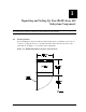
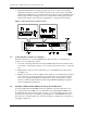
Figure 1–4 PC (Program) Card Slot Location
1.7 Connecting the Controller to Computer
Follow the steps below to connect the RAID Array 410 controller to a communications
(serial) port on your Intel-based system.
1. Locate the connecting cable that came with the RAID subsystem. It has an RJ12 connec-
tor (similar to some telephone plugs) on one end and a 9-pin serial connector on the other
end.
2. Plug the RJ12 connector into the maintenance port on the RAID Array 410 controller
(see Figure 1–4).
3. Plug the serial connector into an available 9-pin serial port on your Intel-based system. If
your system does not have a 9-pin serial port, use the 9-pin to 25-pin adapter supplied
with your StorageWorks RAID Array 410 Subsystem. Note which serial port you use,
because you will need that information when using the RAID 410 Manager program to
set the communications parameters.
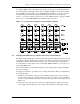
1.8 Installing Additional Disk SBBs in the StorageWorks Enclosure
You may install additional disk SBBs in the StorageWorks enclosure at this time. To im-
prove performance and reliability, we recommend that you install additional SBBs in the
StorageWorks enclosure from left to right, bottom to top (as viewed facing the front of the
enclosure). Doing so improves reliability by permitting you to create RAIDsets that span
more than one controller channel. Also, because more than one channel (bus) is being used,
throughput is improved.