
Computer Hardware User Manual

LPC/FWH Interface Configuration
11-34 Intel® 460GX Chipset Software Developer’s Manual
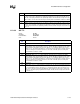
11.2.7.6 General Purpose 0 Enable
Address Offset: OE-0Fh
Attributes: Read/Write
Default Value: 0000h
Size: 16 bits
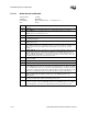
Bit Description
15:12 Reserved.
11 PWR_FAIL: This bit will be set to 1 when a power failure occurs. This is defined as either PWROK
or RSMRST# going inactive unexpectedly. This bit is only set by hardware and can only be reset by
writing a one to this bit position. This bit is not affected by a hard reset caused by a CF9 write. Upon
power up, this bit is set to ‘1’.
10 RI_STS: This bit will be set by 1 to hardware when the RI# input signal goes active. This bit can be
reset only by writing a one to this bit position. This bit is not affected by a hard reset caused by a
CF9 write.
9 Reserved.
8 USB1_STS: This bit is set when the USB controller for ports 0 and 1 needs to cause a wake/break
event. Additionally if the USB1_EN bit is set, the setting of the USB1_STS bit will generate a wake/
break event. This bit is only set by hardware and can only be reset by writing a one to this bit
position. This bit is not affected by a hard reset caused by a CF9 write.
7 THRMOR_STS: This is the thermal interrupt over-ride status. This bit is 1 anytime a thermal over-
ride condition occurs and starts throttling the CPU’s clock at the THRM_DTY ratio. This bit is set by
hardware and can only be cleared by writing a one to this bit position.
6:2 Reserved.
1 NMI_STS: This indicates that an external device generated SERR# or IOCHK#. If the NMI_EN bit is
set in the General Purpose 0 Enable Register, then the setting of this bit will generate an SCI. This
bit is set by hardware and can only be cleared by writing a ‘1’ to this bit position.
0 THRM_STS: This is the thermal interrupt status bit. This bit gets set anytime the THRM# signal is
driven active as defined by the THRM_POL bit. Additionally if the THRM_EN bit is set then the
setting of the THRM_STS bit will additionally generate a power management event (SCI or SMI).
This bit is only set through hardware (the THRM# signal being driven active), and is cleared by
software writing a one to this bit position.
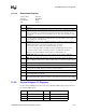
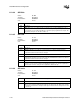
Bit Description
15:13 Reserved.
12 AFTERG3: If set to 0, the IFB will boot the system after the power is returned after a power
failure. If set to 1, the IFB will not boot the system after a power failure and will wait for a wake
event (such as the Power Button being pressed). This bit is automatically set to 1 if a Power
Button Override occurs. Upon power up, this bit is undefined.
11 Reserved.
10 RI_EN: When RI_EN and RI_STS are both set, a Wake event will occur. If RI_EN is not set,
then when RI_STS is set, no Wake event will occur. This bit must be maintained even in the G3
state. This bit is automatically set to 0 if a Power Button Override occurs. Upon power up, this
bit is undefined.
9 Reserved.
8 USB1_EN: This bit is used to enable the setting of the USB1_STS bit to generate a wake/break
event. The USB1_STS bit is set anytime the USB controller for ports 0 and 1 signals a wake/
break event. The value of this bit must be maintained, even through a G3 state. The IFB will not
resume, from USB, after power failure (RSMRST# low). This bit is automatically set to 0 if a
Power Button Override occurs. Upon power up, this bit is undefined.
7:2 Reserved.