Intel® 631xESB/632xESB I/O Controller Hub for Embedded Applications Thermal and Mechanical Design Guidelines February 2007 Order Number: 315263-001
INFORMATION IN THIS DOCUMENT IS PROVIDED IN CONNECTION WITH INTEL® PRODUCTS. NO LICENSE, EXPRESS OR IMPLIED, BY ESTOPPEL OR OTHERWISE, TO ANY INTELLECTUAL PROPERTY RIGHTS IS GRANTED BY THIS DOCUMENT.
Contents—Intel® 6321ESB ICH Contents 1.0 Introduction .............................................................................................................. 5 1.1 Design Flow ........................................................................................................ 5 1.2 Definition of Terms ..............................................................................................7 1.3 Reference Documents ............................................................................
Intel® 6321ESB ICH—Revision History 15 16 Heat Sink Foam Gasket Drawing.................................................................................31 Torsional Clip Drawing ..............................................................................................32 Tables 1 2 3 4 5 6 7 Definition of Terms .................................................................................................... 7 Referenced Documents.....................................................................
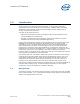
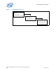
Introduction—Intel® 6321ESB ICH 1.0 Introduction As the complexity of computer systems increases, so do the power dissipation requirements. Care must be taken to ensure that the additional power is properly dissipated. Typical methods to improve heat dissipation include selective use of ducting, and/or passive heatsinks. The goals of this document are to: • Outline the thermal and mechanical operating limits and specifications for the Intel® 6321ESB I/O Controller Hub.
Intel® 6321ESB ICH—Introduction Figure 1.
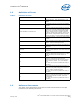
Introduction—Intel® 6321ESB ICH 1.2 Definition of Terms Table 1. Definition of Terms Term 1.3 Definition BLT Bond line thickness. Final settled thickness of the thermal interface material after installation of heatsink. FCBGA Flip Chip Ball Grid Array. A ball grid array packaging technology where the die is exposed on the package substrate.
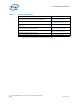
Intel® 6321ESB ICH—Introduction Table 2. Referenced Documents Title Location Intel® 631xESB / 632xESB I/O Controller Hub Datasheet http://www.intel.com/design/ chipsets/datashts/313082.htm Intel® 631xESB / 632xESB I/O Controller Hub Specification Update http://www.intel.com/design/ chipsets/specupdt/313075.
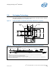
Packaging Technology—Intel® 6321ESB ICH 2.0 Packaging Technology The Intel® 6321ESB I/O Controller Hub component uses a 40 mm x 40 mm, 10-layer FC-BGA3 package (see Figure 2 and Figure 3). Figure 2. Intel® 6321ESB I/O Controller Hub Package Dimensions (Top View) Handling Exclusion Area Die Keepout Area 19.49mm. 10.78mm. 6.17mm. ESB2 Die 20.19mm. 13.99mm. 26.0mm. 30.0mm. 40.0mm. 3.10mm. 26.0mm. 30.0mm. 40.0mm. Figure 3.
Intel® 6321ESB ICH—Packaging Technology Figure 4. Intel® 6321ESB I/O Controller Hub Package Dimensions (Bottom View) AT A AP R A AM N AL AK A H AJ AG AF A AE D A AB C AA 40 + 0.05 Y -A- W V U T R P N M L 19.11 K J H G F E D 35X 1.092 C B A 1 2 3 4 5 6 7 8 9 10 11 12 13 14 15 16 17 18 19 20 21 22 23 24 25 26 27 28 29 30 31 32 33 34 35 A 36 35X 1.092 19.11 B 40 + 0.05 0.2 C A Notes: 1. All dimensions are in millimeters. 2.
Thermal Specifications—Intel® 6321ESB ICH 3.0 Thermal Specifications 3.1 Thermal Design Power (TDP) Analysis indicates that real applications are unlikely to cause the Intel® 6321ESB I/O Controller Hub component to consume maximum power dissipation for sustained time periods. Therefore, in order to arrive at a more realistic power level for thermal design purposes, Intel characterizes power consumption based on known platform benchmark applications.
Intel® 6321ESB ICH—Thermal Simulation 4.0 Thermal Simulation Intel provides thermal simulation models of the Intel® 6321ESB I/O Controller Hub component and associated user's guides to aid system designers in simulating, analyzing, and optimizing their thermal solutions in an integrated, system-level environment. The models are for use with the commercially available Computational Fluid Dynamics (CFD)-based thermal analysis tool Flotherm* (version 5.1 or higher) by Flomerics, Inc*.
Thermal Solution Requirements—Intel® 6321ESB ICH 5.0 Thermal Solution Requirements 5.1 Characterizing the Thermal Solution Requirement The idea of a “thermal characterization parameter” Ψ (the Greek letter psi), is a convenient way to characterize the performance needed for the thermal solution and to compare thermal solutions in identical situations (i.e., heating source, local ambient conditions, etc.).
Intel® 6321ESB ICH—Thermal Solution Requirements Figure 5. Processor Thermal Characterization Parameter Relationships TA ΨSA HEATSINK TIM TS TC ΨCA ΨCS Device Example 1. Calculating the Required Thermal Performance The cooling performance, ΨCA, is defined using the thermal characterization parameter previously described. The process to determine the required thermal performance to cool the device includes: 1. Define a target component temperature TCASE and corresponding TDP. 2.
Thermal Solution Requirements—Intel® 6321ESB ICH C Ψ SA = Ψ CA – Ψ CS = 3.23 – 0.35 = 2.88° --W If the local ambient temperature is relaxed to 45° C, the same calculation can be carried out to determine the new case-to-ambient thermal resistance: T C – T LA C 105 – 45 Ψ CA = ----------------- = -------------- = 4.84° --W 12.4 TDP It is evident from the above calculations that a reduction in the local ambient temperature has a significant effect on the case-to-ambient thermal resistance requirement.
Intel® 6321ESB ICH—Thermal Metrology 6.0 Thermal Metrology The system designer must make temperature measurements to accurately determine the thermal performance of the system. Intel has established guidelines for proper techniques to measure the Intel® 6321ESB I/O Controller Hub die temperatures. Section 6.1 provides guidelines on how to accurately measure the Intel® 6321ESB ICH die temperatures. The flowchart in Figure 6 offers useful guidelines for thermal performance and evaluation. 6.
Thermal Metrology—Intel® 6321ESB ICH Figure 6. Thermal Solution Decision Flowchart Start Attach device to board using normal reflow process. Attach thermocouples using recommended metrology. Setup the system in the desired configuration. Run the Power program and monitor the device die temperature. Select Heatsink Heatsink Required Tdie > Specification? No End Yes 001240 Figure 7. Zero Degree Angle Attach Heatsink Modifications Note: February 2007 Not to scale.
Intel® 6321ESB ICH—Thermal Metrology Figure 8. Zero Degree Angle Attach Methodology (Top View) Die Thermocouple Wire Cement + Thermocouple Bead Substrate Note: Not to scale.
Reference Thermal Solution—Intel® 6321ESB ICH 7.0 Reference Thermal Solution Intel has developed one reference thermal solution to meet the cooling needs of the Intel® 6321ESB I/O Controller Hub component under operating environments and specifications defined in this document. This chapter describes the overall requirements for the Torsional Clip Heatsink reference thermal solution including critical-to-function dimensions, operating environment, and validation criteria.
Intel® 6321ESB ICH—Reference Thermal Solution Figure 9. Torsional Clip Heatsink Measured Thermal Performance Versus Approach Velocity and Target at 65C Local-Ambient 8.000 7.000 Psi-ca (mean plus 2.3 sigma) [C/W] Thermal Target 6.000 Simulation results with EOLife TIM performance 5.000 4.000 3.000 2.000 1.000 0.000 0 50 100 150 200 250 300 350 400 LFM through fin area 7.
Reference Thermal Solution—Intel® 6321ESB ICH Torsional Clip Heatsink Volumetric Envelope for the Intel® 6321ESB I/O Controller Hub 4.30 2.61mm. mm 4.30mm ESB2 Passive Heatsink 33.30 mm. 21.33mm 21.33 mm Figure 10. Die + TIM FCBGA + Solder Balls Motherboard 42.30 mm 42.30 mm. ESB2 Passive Heatsink 7.4 42.30 mm. 42.30 mm TNB Heatsink Board-Level Components Keepout Dimensions The location of holes pattern and keepout zones for the reference thermal solution are shown in Figure 11.
Intel® 6321ESB ICH—Reference Thermal Solution 7.5 Torsional Clip Heatsink Thermal Solution Assembly The reference thermal solution for the Intel® 6321ESB ICH component is a passive heatsink with thermal interface. It is attached using a clip with each end hooked through an anchor soldered to the board. Figure 12 shows the reference thermal solution assembly and associated components.
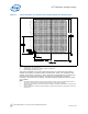
Reference Thermal Solution—Intel® 6321ESB ICH Figure 11. Torsional Clip Heatsink Board Component Keepout Note: 7.5.1 Same Keepout zones as Intel ® 3100 Chipset Heatsink Orientation Since this solution is based on a unidirectional heatsink, mean airflow direction must be aligned with the direction of the heatsink fins.
Intel® 6321ESB ICH—Reference Thermal Solution Figure 12. Torsional Clip Heatsink Assembly 7.5.2 Mechanical Interface Material There is no mechanical interface material associated with this reference solution. 7.5.3 Thermal Interface Material A Thermal Interface Material (TIM) provides improved conductivity between the die and heatsink. The reference thermal solution uses Honeywell* PCM45F, 0.254 mm (0.010 in.) thick, 15 mm x 15 mm (0.59 in. x 0.59 in.) square.
Reference Thermal Solution—Intel® 6321ESB ICH Life value is the predicted TIM performance when the product and TIM reaches the end of its life. The heatsink clip provides enough pressure for the TIM to achieve End of Line thermal resistance of 0.345 °C x in2/W and End of Life thermal resistance of 0.459°C in2/W. Table 5. Honeywell PCM45 F TIM Performance as a Function of Attach Pressure Thermal Resistance (°C × in2)/W Pressure on IHS(psi) End of Line End of Life 2.18 4.35 Note: 7.5.
Intel® 6321ESB ICH—Reliability Guidelines 8.0 Reliability Guidelines Each motherboard, heatsink and attach combination may vary the mechanical loading of the component. Based on the end user environment, the user should define the appropriate reliability test criteria and carefully evaluate the completed assembly prior to use in high volume. Some general recommendations are shown in Table 6. Table 6.
Thermal Solution Component Suppliers—Intel® 6321ESB ICH Appendix A Thermal Solution Component Suppliers A.1 Torsional Clip Heatsink Thermal Solution Intel Part Number Part Contact Information AdvancedTCA* and Embedded Form Factor Heat Sink N/A ECB-00306-01-GP (Aluminum) Wendy Lin 510-770-8566, x211 Wendy@coolermaster.com Thermal Interface (PCM45F) N/A Honeywell* PCM45F Paula Knoll 858-705-1274 paula.knoll@honeywell.
Intel® 6321ESB ICH—Mechanical Drawings Appendix B Mechanical Drawings Table 7 lists the mechanical drawings included in this appendix. Table 7.
Mechanical Drawings—Intel® 6321ESB ICH Figure 13.
Intel® 6321ESB ICH—Mechanical Drawings Figure 14.
Mechanical Drawings—Intel® 6321ESB ICH Figure 15.
Intel® 6321ESB ICH—Mechanical Drawings Figure 16.