
64-bit Intel Xeon Processor with 2MB L2 Cache Thermal/Mechanical Design Guidelines

64-bit Intel® Xeon™ Processor with 2MB L2 Cache Thermal/Mechanical Design Guidelines 13
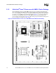
Thermal/Mechanical Reference Design
The package includes an integrated heat spreader (IHS). The IHS transfers the non-uniform heat
from the die to the top of the IHS, out of which the heat flux is more uniform and spread over a
larger surface area (not the entire IHS area). This allows more efficient heat transfer out of the
package to an attached cooling device. The IHS is designed to be the interface for contacting a
heatsink. Details can be found in the 64-bit Intel
®
Xeon™ Processor with 2MB L2 Cache
Datasheet.
The processor connects to the baseboard through a 604-pin surface mount, zero insertion force
(ZIF) socket. A description of the socket can be found in the mPGA604 Socket Design Guidelines.
The processor package has mechanical load limits that are specified in the processor datasheet and
in Table 2-1. These load limits should not be exceeded during heatsink installation, removal,
mechanical stress testing, or standard shipping conditions. For example, when a compressive static
load is necessary to ensure thermal performance of the Thermal Interface Material (TIM) between
the heatsink base and the IHS, it should not exceed the corresponding specification given in the
processor datasheet.
The heatsink mass can also add additional dynamic compressive load to the package during a
mechanical shock event. Amplification factors due to the impact force during shock must be taken
into account in dynamic load calculations. The total combination of dynamic and static
compressive load should not then exceed the processor compressive dynamic load specified in the
datasheet and in Table 2-1 during a vertical shock. It is not recommended to use any portion of the
processor substrate as a mechanical reference or load- bearing surface in either static or dynamic
compressive load conditions.
2.1.3 64-bit Intel
®
Xeon™ Processor with 2MB L2 Cache
Considerations
An attachment mechanism must be designed to support the heatsink since there are no features on
the mPGA604 socket to directly attach a heatsink. In addition to holding the heatsink in place on
top of the IHS, this mechanism plays a significant role in the robustness of the system in which it is
implemented, in particular:
• Ensuring thermal performance of the TIM applied between the IHS and the heatsink. TIMs,
especially ones based on phase change materials, are very sensitive to applied pressure: the
higher the pressure, the better the initial performance. TIMs such as thermal greases are not as
sensitive to applied pressure. Refer to Section 2.4.2 for information on tradeoffs made with
TIM selection. Designs should consider possible decrease in applied pressure over time due to
potential structural relaxation in enabled components.
• Ensuring system electrical, thermal, and structural integrity under shock and vibration events.
The mechanical requirements of the attach mechanism depend on the weight of the heatsink
and the level of shock and vibration that the system must support. The overall structural design
of the baseboard and system must be considered when designing the heatsink attach
mechanism. Their design should provide a means for protecting mPGA604 socket solder
joints as well as preventing package pullout from the socket.
Note: The load applied by the attachment mechanism must comply with the package specifications, along
with the dynamic load added by the mechanical shock and vibration requirements, as identified in
Section 2.1.1.
A potential mechanical solution for heavy heatsinks is the direct attachment of the heatsink to the
chassis pan. In this case, the strength of the chassis pan can be utilized rather than solely relying on
the baseboard strength. In addition to the general guidelines given above, contact with the
baseboard surfaces should be minimized during installation in order to avoid any damage to the
baseboard.